
Mixed fuel vacuum burner-reactor

a technology of vacuum burner and mixed fuel, which is applied in the direction of lighting and heating apparatus, combustion types, combustion processes, etc., can solve the problems of residue and cleaning difficulties, -quality, clean-burning fuels, and still may not achieve the complete burning of all fuel, etc., and achieve the effect of efficient burning of mixed fuels

Active Publication Date: 2014-08-21
DE LA SOVERA JORGE
View PDF5 Cites 21 Cited by
  • Summary
  • Abstract
  • Description
  • Claims
  • Application Information

AI Technical Summary

Benefits of technology

The present patent describes a mixed-fuel vacuum burner-reactor that can efficiently burn a variety of fuels including gas and liquid. The reactor has a conical combustion chamber with directing blades that create three vortices of fuel that rotate and a secondary combustion chamber to sustain the rotation. The reactor also has an intake manifold for introducing fuels and compressed air, and injectors for introducing a second set of fuels in a direction opposite to the first set. The technical effects of the invention include improved mixing of fuels, reduced emissions, and efficient combustion in a compact design.

Problems solved by technology

While this accomplishes the goal of increased air-fuel mixture, an igniter is required for sustaining the combustion and this still may not accomplish complete in burning all of the fuel.
Solutions that employ guide pieces and flow spaces (i.e., reactors) can also be used, but suffer from residue and cleaning difficulties, particularly when used with lower-quality fuels.
However, these solutions also require high-quality, clean-burning fuels and suffer from maintenance issues resulting from residues.

Method used


Image

  • Mixed fuel vacuum burner-reactor
  • Mixed fuel vacuum burner-reactor
  • Mixed fuel vacuum burner-reactor

Examples


Embodiment Construction

[0016]The presently depicted and disclosed burner-reactor will be described with respect to an exemplary embodiment. The disclosure should not be interpreted to be limiting or to require in the invention all described features. Where possible, like elements will be numbered in a like fashion for clarity. Illustrative alternatives will be given where applicable, but other equivalents may be readily apparent and are contemplated where appropriate.

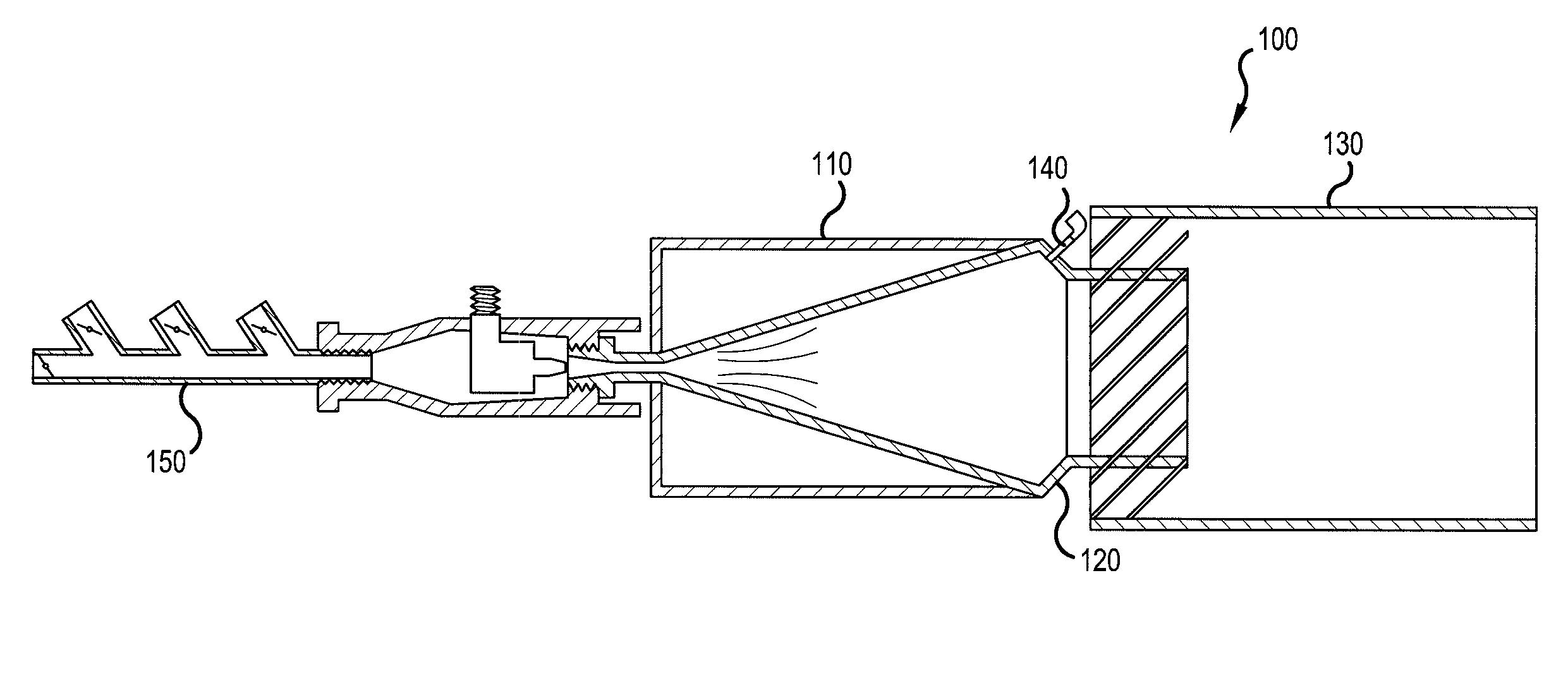
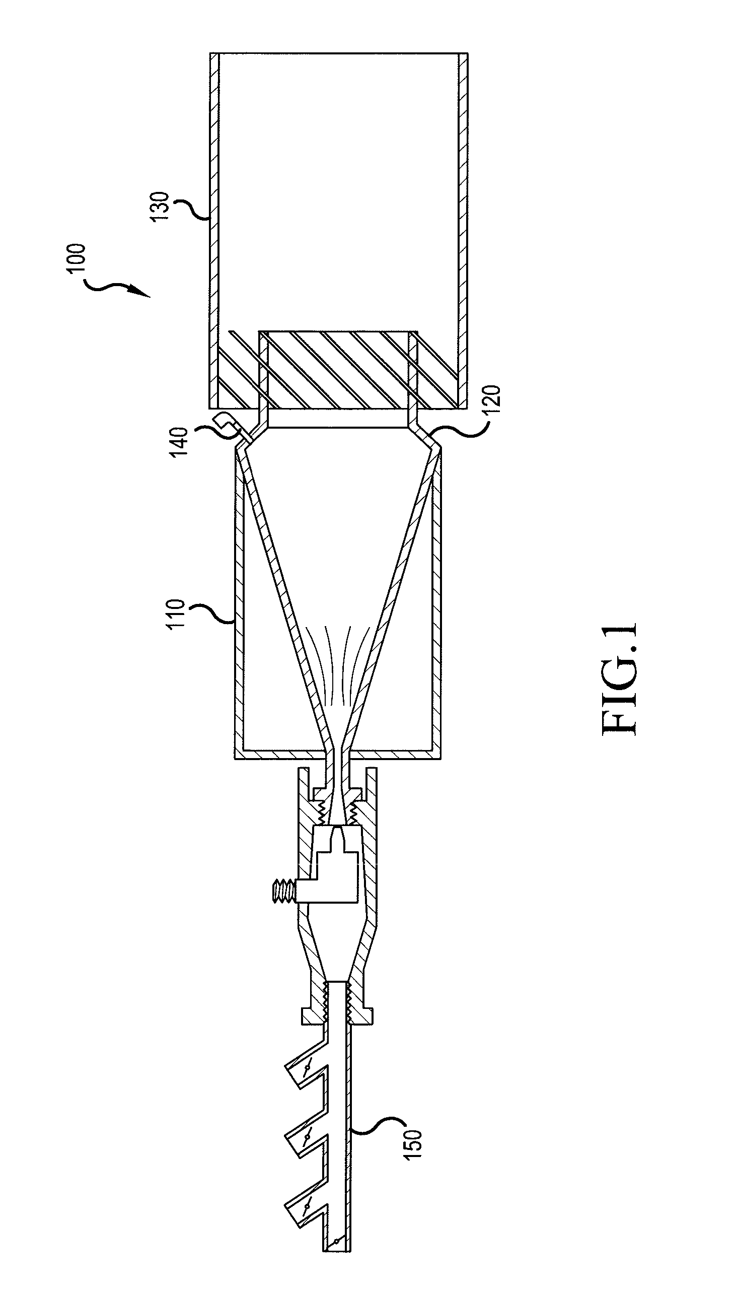
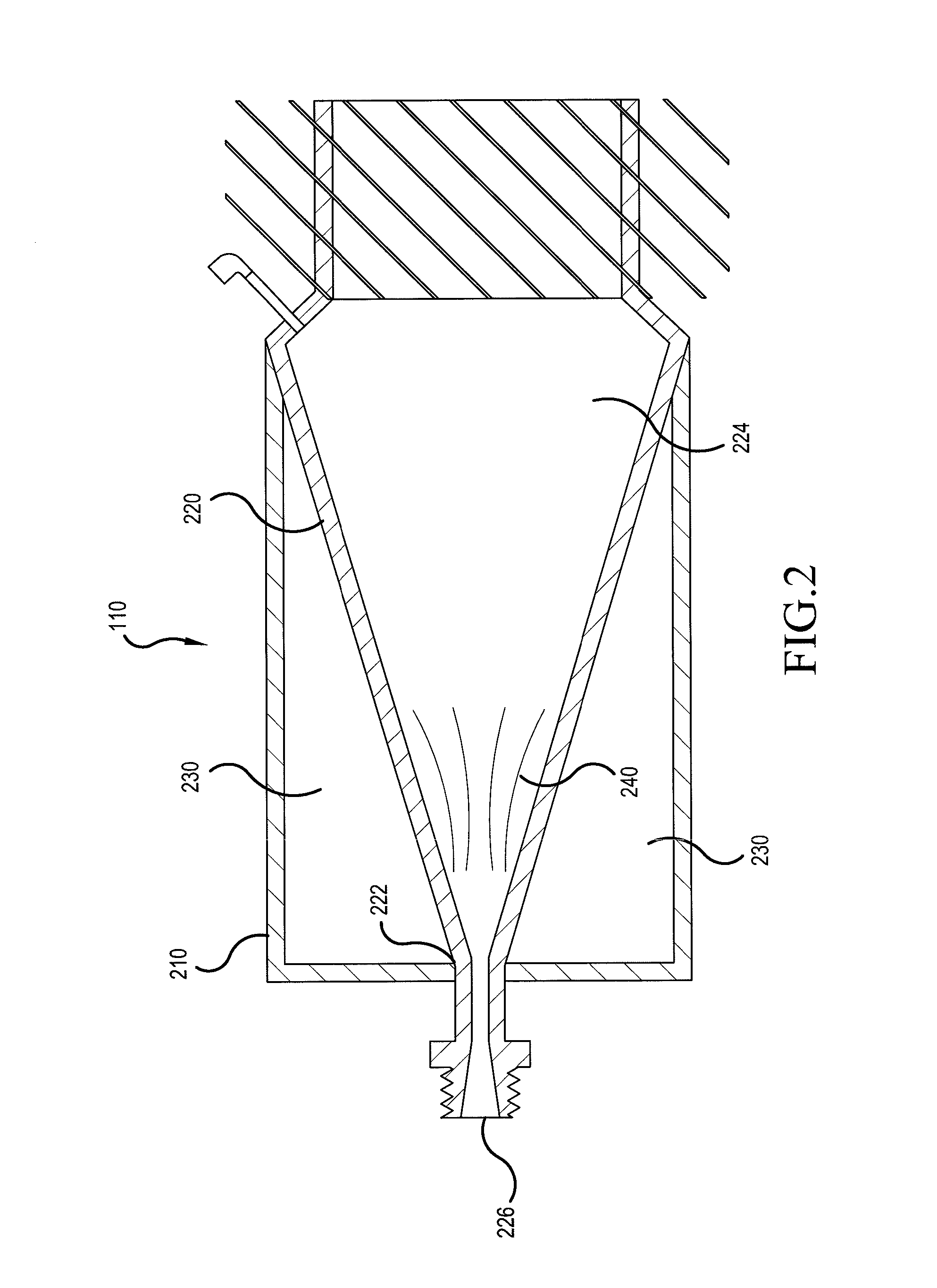
[0017]FIG. 1 depicts a cross-section of a mixed fuel vacuum burner-reactor 100 according to embodiments of the present disclosure. Burner-reactor 100 includes a primary combustion chamber 110 connected to a reduction nozzle 120, which is in turn connected to a secondary combustion chamber 130. Burner-reactor 100 further includes injectors 140 placed perpendicularly on reduction nozzle 120. Primary combustion chamber 110 is also connected to an intake manifold 150 opposite the reduction nozzle 120. Each of the elements above will be described ...


PUM


Abstract

A mixed-fuel vacuum burner-reactor includes a primary combustion chamber having a conical interior and a first set of directing blades. The conical interior is connected to an intake manifold on one end and a reduction nozzle on the other end. Injectors are mounted perpendicularly to the reduction nozzle to inject a second fuel into the primary combustion chamber. The reduction nozzle is connected to a cylindrical secondary combustion chamber having a second set of directing blades configured to direct air into the secondary combustion chamber. Methods of efficiently burning mixed fuels in a triple-vortex vacuum burner-reactor are also disclosed. Vacuum conditions are created and fuels are introduced into a conical primary combustion chamber. The fuels are passed over a first set of directing blades to form three vortices before additional fuels are injected in a direction opposite to a direction of rotation of the first set of fuels.

Description

BACKGROUND[0001]Burners are devices that burn fuel to generate heat in industrial settings, such as those used for generation of electricity, smelting of metals and other materials, and used for processing of chemicals and other substances. Due to incomplete combustion in previously designed burners, newer examples use generators inside the burner to create a vortex (i.e., rotating mixture of air and fuels) in order to supply more oxidants for the combustion process. While this accomplishes the goal of increased air-fuel mixture, an igniter is required for sustaining the combustion and this still may not accomplish complete in burning all of the fuel. Solutions that employ guide pieces and flow spaces (i.e., reactors) can also be used, but suffer from residue and cleaning difficulties, particularly when used with lower-quality fuels. Likewise, reactor solutions that employ a premix burner and a flame tube allow for staged combustion in individual mixers. However, these solutions als...

Claims


Application Information

Patent Timeline
Patent Type & Authority Applications(United States)
IPC IPC(8): F23G5/12F23G7/00F23C5/32F23C1/08F23C3/00
CPCF23G5/12F23C1/08F23G7/008F23C5/32F23C3/00F23L9/02F23C6/042F23D14/04F23D17/002F23C2201/301F23D2900/14241F23D2900/14701F23C6/047
Inventor DE LA SOVERA, JORGE
Owner DE LA SOVERA JORGE
Learn More