Check patentability & draft patents in minutes with Patsnap Eureka AI!

Procedure for operating a transmission device, particularly a 9-speed-transmission

a transmission device and transmission technology, applied in the direction of mechanical equipment, instruments, transportation and packaging, etc., can solve the problems of reducing the overall efficiency of an automatic transmission to an unwanted extent, and the form-locking shift element cannot be transferred to the disengaged operating sta

Active Publication Date: 2014-08-21
ZF FRIEDRICHSHAFEN AG
View PDF6 Cites 4 Cited by
  • Summary
  • Abstract
  • Description
  • Claims
  • Application Information

AI Technical Summary

Benefits of technology

The present invention provides a method for operating a transmission device, particularly a 9-speed transmission, which can be transferred into various operating states by actuating shift elements. This method prevents unauthorized gear shifts and ensures that the transmission device operates safely and efficiently. The method uses a sensor device to detect the current switching state of a form-locking shift element and ensures that the shift element is in the disengaged operating state or the engaged operating state. The method also includes a timer to transfer the transmission device to a safe operating state if the form-locking shift element has not been transferred to the disengaged operating state after a predefined shift time. The method can be easily adapted based on various operating parameters such as temperature and oil viscosity. Overall, this method provides a reliable and efficient way to operate transmission devices and prevent unauthorized gear shifts.

Problems solved by technology

Disadvantageously, friction-locking shift elements in the disengaged operating state cause drag torques, however, which lower an overall efficiency of an automatic transmission to an unwanted extent.
Under certain circumstances, the form-locking shift element cannot be transferred to the disengaged operating state due to an excessively rapid or faulty build-up of the torque present in the region of the form-locking shift element, for example during an upshift or a faulty reduction of the torque that is present, for example during a gear disengagement.

Method used


Image

  • Procedure for operating a transmission device, particularly a 9-speed-transmission
  • Procedure for operating a transmission device, particularly a 9-speed-transmission
  • Procedure for operating a transmission device, particularly a 9-speed-transmission

Examples


Embodiment Construction

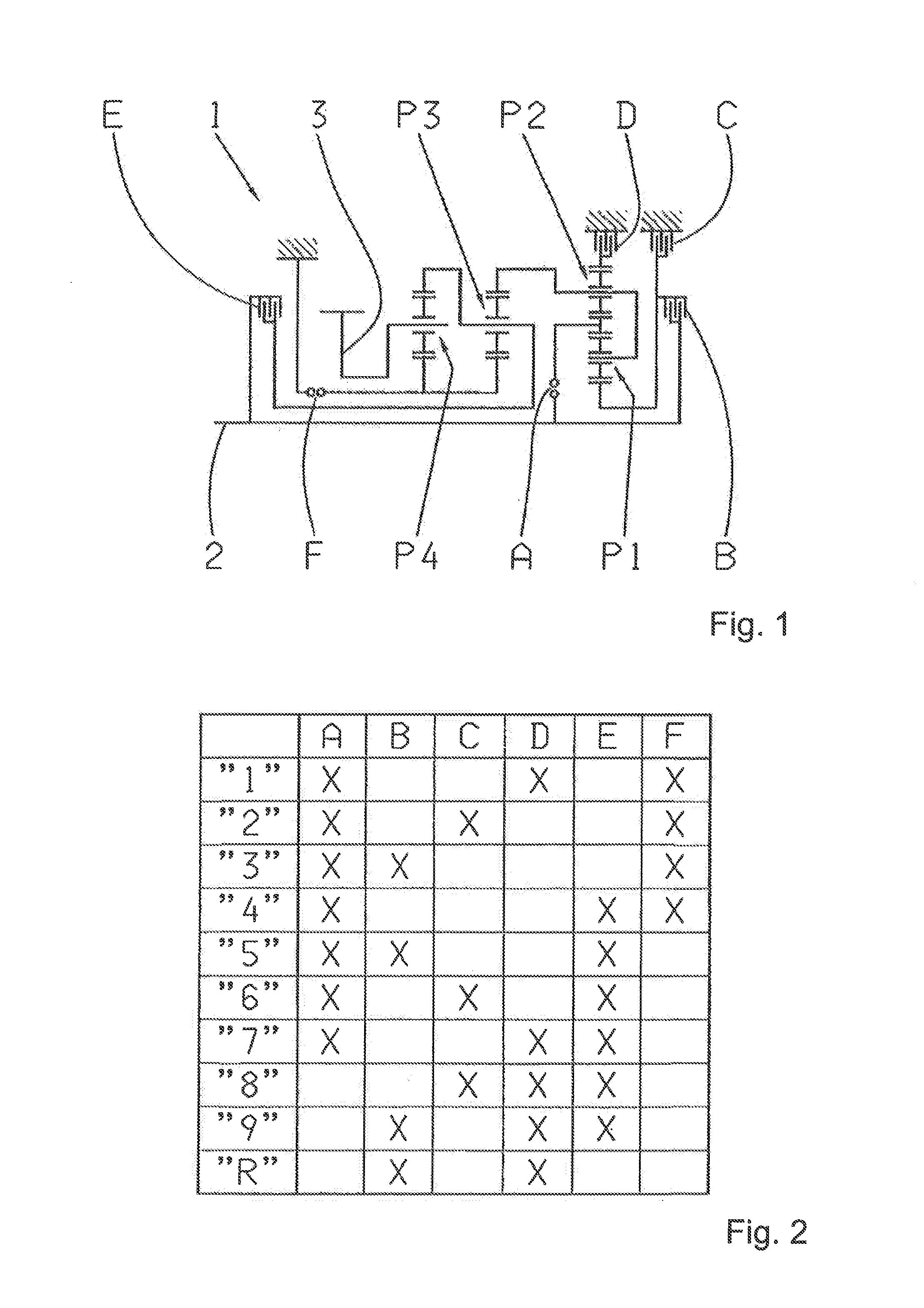
[0033]FIG. 1 shows a gearwheel scheme of a transmission device 1 or a 9-speed transmission that is basically known from DE 10 2008 000 429 A1. The transmission device 1 comprises a drive shaft 2 and an output shaft 3 which, in the installed state in a vehicle, is connected to an output drive of the vehicle, while the drive shaft 2 is operatively connected to a drive motor.

[0034]The transmission device 1 also comprises four planetary gear sets P1 to P4, wherein the first and second planetary gear sets P1, P2, which are preferably in the form of minus planetary gear sets, form a shiftable, input-side gear set, while the third and fourth planetary gear sets P3 and P4 are the main gear set. The transmission device 1 also comprises six shift elements A to F, of which shift elements C, D and F are designed as brakes, and the shift elements A, B and E are designed as shifting clutches.

[0035]Using the shift elements A to F, selective shifting of nine forward gears “1” to “9” and one reverse...


PUM


Abstract

A method for operating a 9-speed transmission which changes operating states by actuating shift elements. At least one of the shift elements is a form-locking shift element, which disengages to implement a defined transmission operating state during which the power flow, between transmission input and output shafts, is present or interrupted. A sensor is associated with the locking shift element. An operating state of the locking shift element can be determined by the sensor, Upon a request to disengage the locking shift element, a disengagement control signal is generated and the locking shift element is actuated in the disengagement direction, depending on the disengagement control signal. The transmission is shifted to a safe operating state, in which at least the transmission output shaft can rotate, when an engaged operating state of the locking shift element is determined by the sensor even though a disengagement control signal was generated.

Description

[0001]This application claims priority from German patent application serial no. 10 2013 202 707.9 filed Feb. 20, 2013.FIELD OF THE INVENTION[0002]The invention relates to a method for operating a transmission device, in particular a 9-speed transmission.BACKGROUND OF THE INVENTION[0003]Document DE 10 2005 002 337 A1 makes known a transmission device, which is designed as an 8-speed, multi-stage transmission having friction-locking shift elements, such as multi-disk clutches and multi-disk brakes. In the event of a shift request for a transmission ratio change in the transmission device, at least one friction-locking shift element—which is engaged in the power flow of the transmission device in order to implement the actual transmission ratio currently engaged in the transmission device—must be disengaged from the power flow of the transmission device, while at least one further friction-locking shift element—which is disengaged from the power flow of the transmission device during ...

Claims


Application Information

Patent Timeline
IPC IPC(8): F16H61/02
CPCF16H61/0213F16H61/0204F16H61/12F16H61/682F16H2061/1224F16H2061/1232F16H2061/1276F16H2200/2094F16H2061/1272F16H61/686F16H2059/6807F16H2061/1204F16H2200/0065F16H2200/201F16H2200/2046
Inventor ARNOLD, JORGMIHATSCH, GEORG
Owner ZF FRIEDRICHSHAFEN AG
Features
  • R&D
  • Intellectual Property
  • Life Sciences
  • Materials
  • Tech Scout
  • Unparalleled Data Quality
  • Higher Quality Content
  • 60% Fewer Hallucinations
Learn More