
Multi-path id routing in a pcie express fabric environment

a multi-path id and fabric environment technology, applied in the direction of electrical instruments, electric digital data processing, electrical equipment, etc., can solve the problems of system cost and power envelope that other fabric choices cannot achieve, and the pcie standard provides no means to handle routing over multiple paths, and no known solution

Inactive Publication Date: 2014-08-21
AVAGO TECH WIRELESS IP SINGAPORE PTE
View PDF2 Cites 110 Cited by
  • Summary
  • Abstract
  • Description
  • Claims
  • Application Information

AI Technical Summary

Benefits of technology

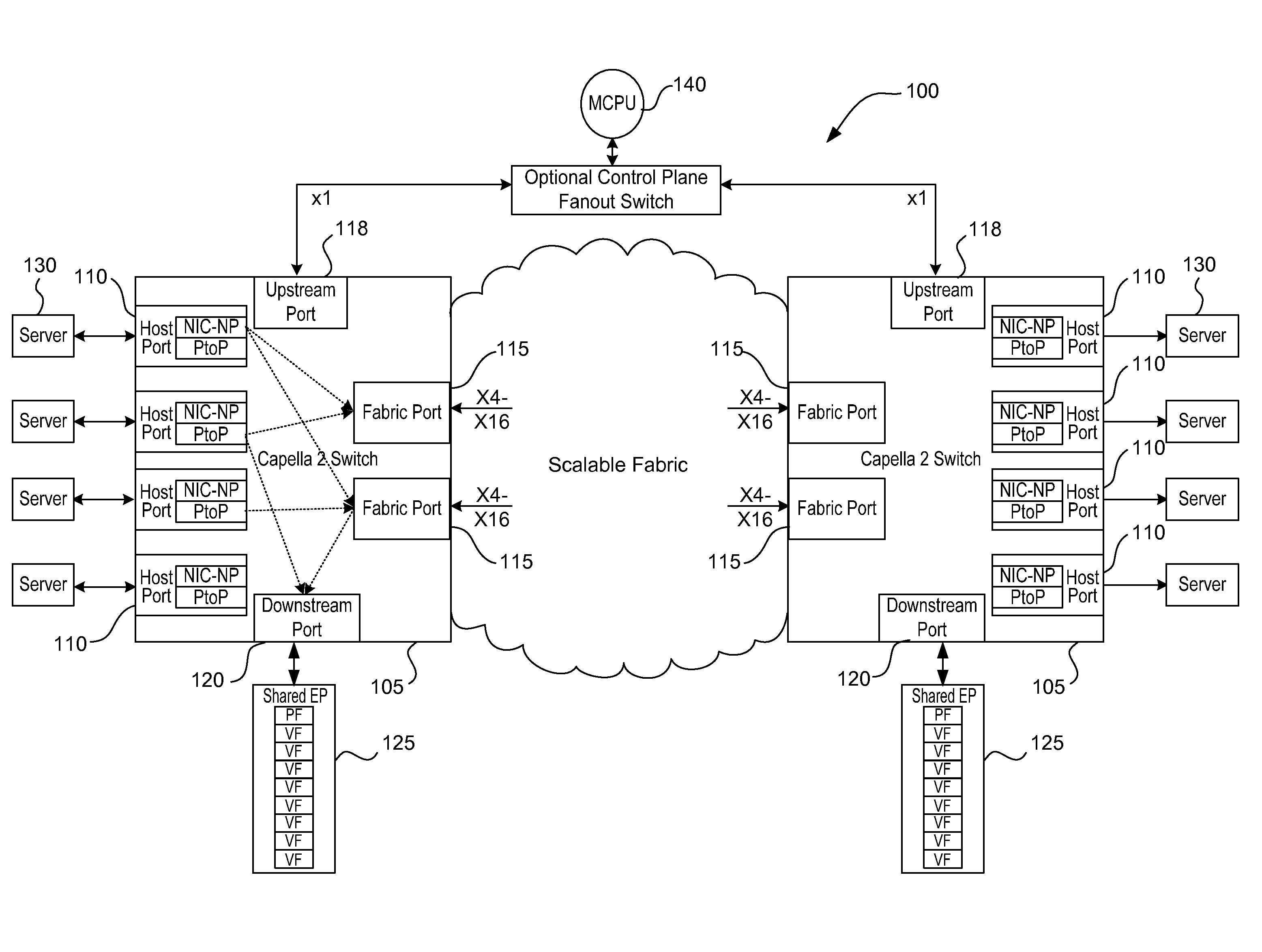
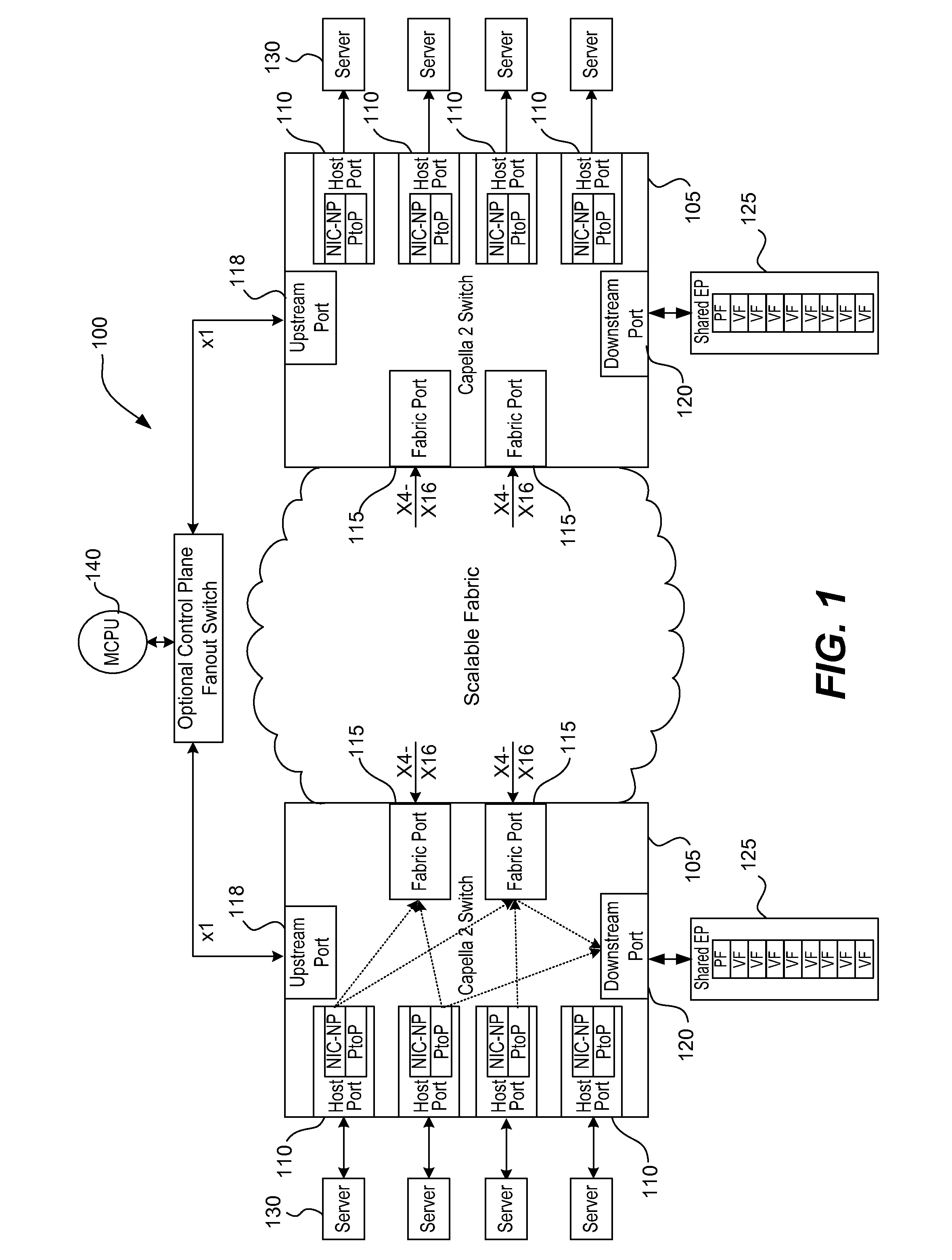
This patent describes a way to route traffic in a switch fabric that has multiple routing paths. It explains how to add a special identifier (ID) to packets of data that enter the switch fabric, which helps to identify and route the data to its destination. The system also uses a lookup table to define this ID. The patent also describes how to remove the ID from the data packet when it exits the switch fabric. Additionally, the patent explains how to select the best routing path for data packets based on their order, unorder, and level of congestion. Overall, this patent provides a technical solution for more efficiently routing data packets in switch fabric networks.

Problems solved by technology

It has near-universal connectivity with silicon building blocks, and offers a system cost and power envelope that other fabric choices cannot achieve.
However, the PCIe standard provides no means to handle routing over multiple paths, or for handling congestion while doing so.
There are no known solutions in the prior art that extend PCIe to multiple paths.

Method used


Image

  • Multi-path id routing in a pcie express fabric environment
  • Multi-path id routing in a pcie express fabric environment
  • Multi-path id routing in a pcie express fabric environment

Examples


case1

[0185] The TLP is an ordered TLP. D-LUT[DB] tells us to use choice1. Regardless of congestion feedback, a decision to route to choice1 leads to Sw-11 and even worse congestion.

case2

[0186] The TLP is an unordered TLP. D-LUT[DB] shows that all 3 choices 1, 2, and 3 are unmasked but 4-12 are masked off. Normally we would want to route to Sw-11 as that is the next switch to spray unordered medium traffic to. However, a check on NextHop[DB] shows that choice2's next hop port would lead to congestion. Furthermore choice3 has local congestion. This leaves one ‘good choice’, choice1. The decision is then made to route to Sw-10 and update the last picked to be Sw-10.

case3

[0187] A new medium priority unordered TLP arrives and targets Sw-04 destination bus DC. D-LUT[DC] shows all 3 choices are unmasked. Normally we want to route to Sw-11 as that is the next switch to spray unordered traffic to. NextHop[DC] shows that choice2's next hop port is not congested, choice2 locally is not congested, and so we route to Sw-11 and update the last routed state to be Sw-11.

5. Route Choice to Port Mapping

[0188]The final step in routing is to translate the route choice to an egress port number. The choice is essentially a logical port. The choice is used to index table below to translate the choice to a physical port number. Separate such tables exist for each station of the switch and may be encoded differently to provide a more even spreading of the traffic.

TABLE 5Route Choice to Port Mapping TableDefaultValueAttributeEEPROMResetOffset(hex)(MCPU)WritableLevelRegister or Field NameDescription1000hChoice_mapping_0_3Choice to port mappingentries for choices 0 to 3 [4...


PUM


Abstract

PCIe is a point-to-point protocol. A PCIe switch fabric has multi-path routing supported by adding an ID routing prefix to a packet entering the switch fabric. The routing is converted within the switch fabric from address routing to ID routing, where the ID is within a Global Space of the switch fabric. Rules are provided to select optimum routes for packets within the switch fabric, including rules for ordered traffic, unordered traffic, and for utilizing congestion feedback. In one implementation a destination lookup table is used to define the ID routing prefix for an incoming packet. The ID routing prefix may be removed at a destination host port of the switch fabric.

Description

CROSS REFERENCE TO RELATED APPLICATIONS[0001]The present application is a continuation-in-part of U.S. patent application Ser. No. 13 / 660,791, filed on Oct. 25, 2012, entitled, “METHOD AND APPARATUS FOR SECURING AND SEGREGATING HOST TO HOST MESSAGING ON PCIe FABRIC.”[0002]This application incorporates by reference, in their entirety and for all purposes herein, the following U.S. patent and application Ser. No. 13 / 624,781, filed Sep. 21, 2012, entitled, “PCI EXPRESS SWITCH WITH LOGICAL DEVICE CAPABILITY”; Ser. No. 13 / 212,700 (now U.S. Pat. No. 8,645,605), filed Aug. 18, 2011, entitled, “SHARING MULTIPLE VIRTUAL FUNCTIONS TO A HOST USING A PSEUDO PHYSICAL FUNCTION”; and Ser. No. 12 / 979,904 (now U.S. Pat. No. 8,521,941), filed Dec. 28, 2010, entitled “MULTI-ROOT SHARING OF SINGLE-ROOT INPUT / OUTPUT VIRTUALIZATION.”[0003]This application incorporates by reference, in its entirety and for all purposes herein, the following U.S. Pat. No. 8,553,683, entitled “THREE DIMENSIONAL FAT TREE NET...

Claims


Application Information

Patent Timeline
IPC IPC(8): G06F13/40
CPCG06F13/4027G06F21/85G06F2221/2129G06F2221/2141G06F2221/2149G06F13/4022H04L45/74
Inventor REGULA, JACKDODSON, JEFFREY M.SUBRAMANIYAN, NAGARAJAN
Owner AVAGO TECH WIRELESS IP SINGAPORE PTE
Learn More