
Laser-ignition combustor for gas turbine engine

Active Publication Date: 2014-08-28
PRATT & WHITNEY CANADA CORP
View PDF22 Cites 4 Cited by
  • Summary
  • Abstract
  • Description
  • Claims
  • Application Information

AI Technical Summary

Benefits of technology

The invention relates to a combustor for a gas turbine engine and a gas turbine engine comprising the combustor. The combustor has a casing forming a pressure vessel with an inlet for receiving compressed air and a liner holding a subchamber of the pressure vessel. The liner has a plurality of apertures formed therethrough and allowing controlled fluid flow communication of the compressed air from the plenum into the subchamber. The gas turbine engine also includes a turbine section for extracting energy from the hot stream of combustion gasses. The patent’s technical effects include improved fuel combustion, reduced emissions, improved operability, and improved performance of the gas turbine engine.

Problems solved by technology

The end of the strut mounted to the liner needed to accommodate the relative thermal growth of the liner, which was achieved by a floating collar but nonetheless produced fretting and required regular maintenance.

Method used


Image

  • Laser-ignition combustor for gas turbine engine
  • Laser-ignition combustor for gas turbine engine
  • Laser-ignition combustor for gas turbine engine

Examples


Embodiment Construction

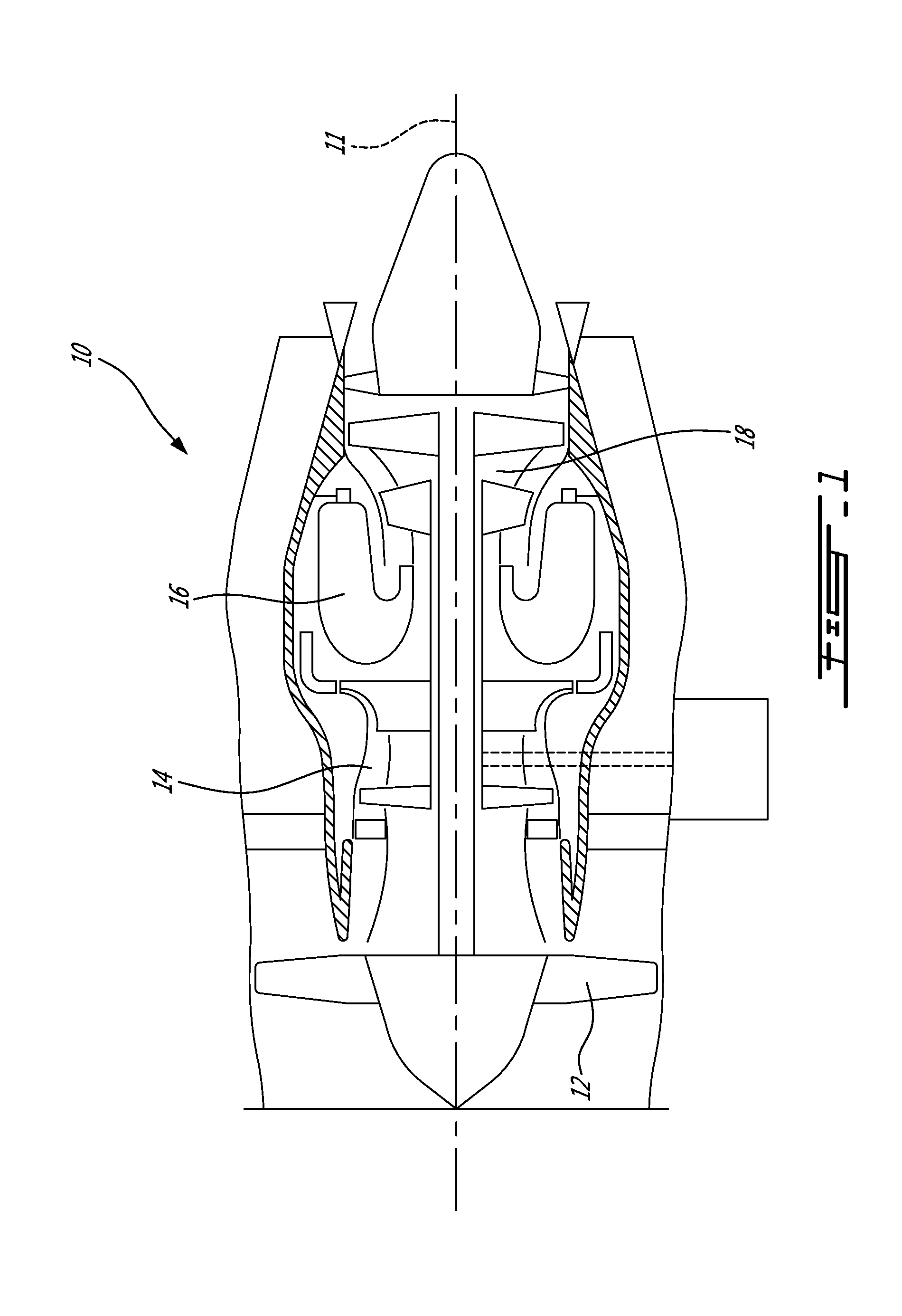
[0011]FIG. 1 illustrates a turbofan gas turbine engine 10 of a type preferably provided for use in subsonic flight, generally comprising in serial flow communication a fan 12 through which ambient air is propelled, a multistage compressor 14 for pressurizing the air, a combustor 16 in which the compressed air is mixed with fuel and ignited for generating an annular stream of hot combustion gases, and a turbine section 18 for extracting energy from the combustion gases. The fan 12, compressor 14, combustor 16 and turbine section 18 are generally annular around a main axis 11 of the gas turbine engine 10.

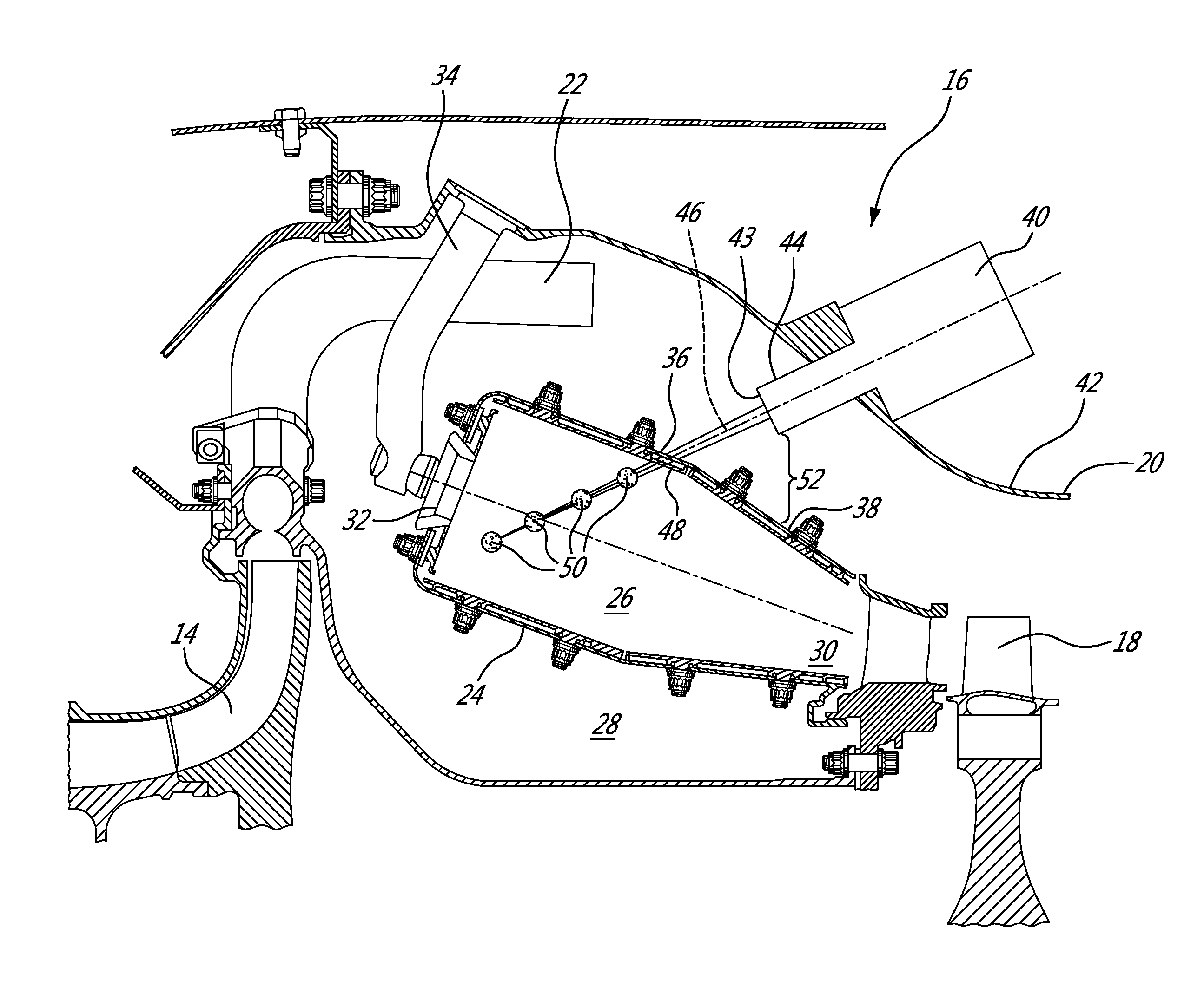
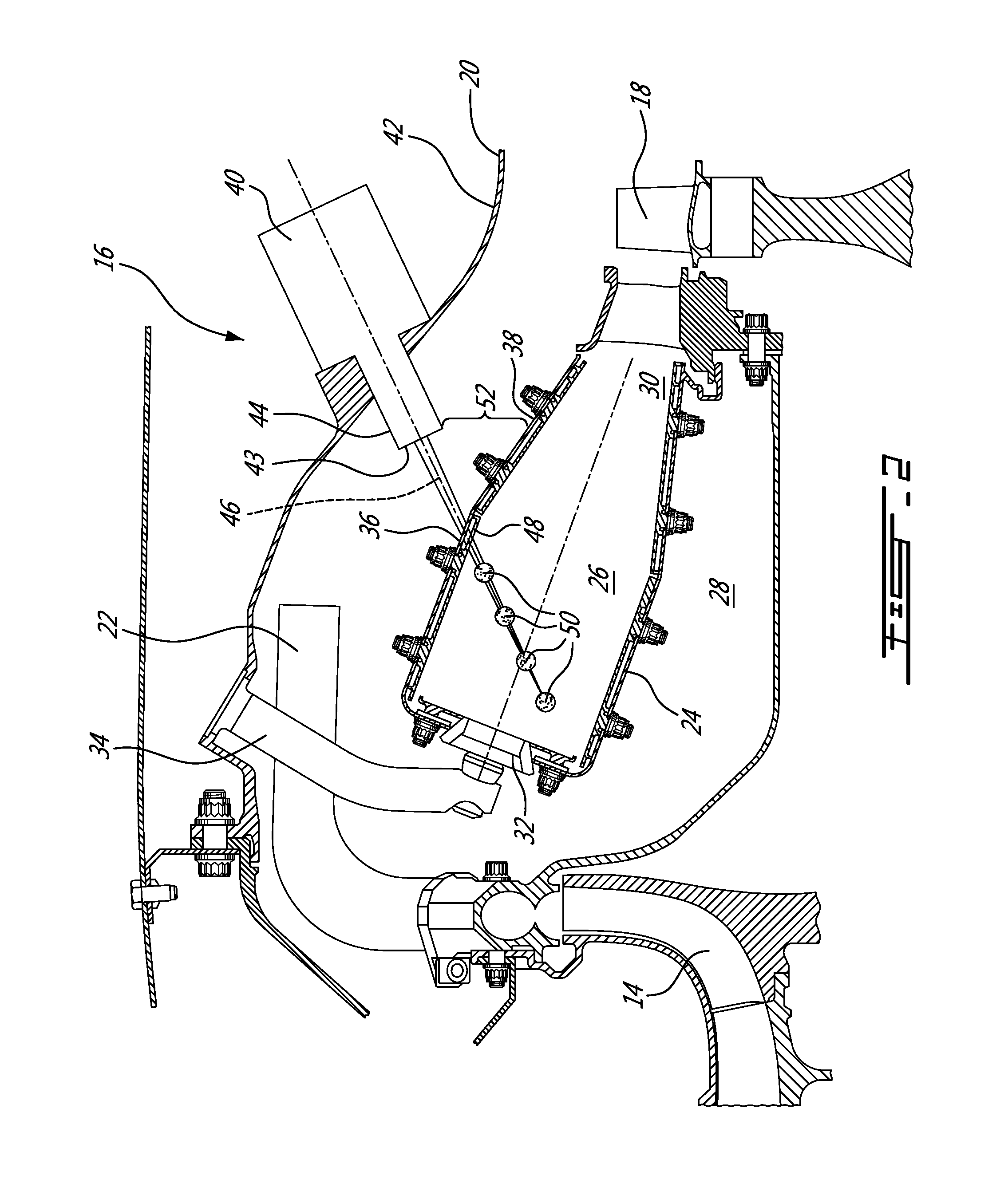
[0012]The enlarged view provided in FIG. 2 shows a combustor 16 in greater detail. More particularly, as can be seen in the figure, the combustor 16 generally includes a case or casing 20 forming an outer shell and serving as a pressure vessel to withstand the important pressure difference which can exist between the compressed air and the environment. To this end, the casing 20 is en...


PUM


Abstract

The combustor has a laser ignitor mounted to the casing, remotely from the liner of the combustion chamber. The laser ignitor has an igniter beam path for igniting the fuel and air mixture in the combustion chamber, the igniter beam path extending at least partially across the air plenum surrounding the liner and into the combustion chamber through a corresponding beam path aperture provided in the liner.

Description

TECHNICAL FIELD[0001]The application relates generally to gas turbine engines and, more particularly, to combustors therefore which have laser igniters.BACKGROUND OF THE ART[0002]Spark plugs have been the traditional means to ignite the fuel / air mixture inside combustion chambers of gas turbine engines for many decades. The spark plugs were housed in struts extending across the compressed air plenum, between the combustor casing and the combustion chamber liner. The liner is subjected to extreme high temperatures and associated thermal growth whereas the casing is subjected to relatively cool compressed air and therefore to much less thermal growth. The end of the strut mounted to the liner needed to accommodate the relative thermal growth of the liner, which was achieved by a floating collar but nonetheless produced fretting and required regular maintenance.[0003]In more recent years, spark plugs have been replaced by laser igniters. The laser igniters were at least partially house...

Claims


Application Information

Patent Timeline
IPC IPC(8): F02C7/264
CPCF02C7/264F23R3/002F23R3/50F23R2900/00006F23Q13/005F02P23/04F02C7/266
Inventor DAVENPORT, NIGELPATEL, BHAWANHAWIE, EDUARDO
Owner PRATT & WHITNEY CANADA CORP
Learn More