Portable Ice Making Apparatus Having a Bypass Tube

a technology of bypass tube and ice making apparatus, which is applied in the direction of refrigeration safety arrangement, light and heating apparatus, refrigeration components, etc., can solve the problems of little more time, damage to the compressor, and the conventional apparatus does not have a separator to collect liquefied refrigerant, etc., to achieve precise heat control, and fast freezing and heating operations

Inactive Publication Date: 2014-08-28
SUL DONG HWAN
View PDF10 Cites 10 Cited by
  • Summary
  • Abstract
  • Description
  • Claims
  • Application Information

AI Technical Summary

Benefits of technology

[0009]The object of this invention is to provide a more efficient portable onsite ice making apparatus. The switching means controls the flow of the refrigerant and thus changes the operating modes between the freezing and heating modes. The switching means allows only one flow direction of the refrigerant: to the condenser or to the bypass tube. This structure of the switching means also contributes to faster freezing and heating operations:
[0010]Another object of this invention is to provide a portable onsite ice making apparatus which has a faster freezing / heating operation. The bypass tube is configured to have a capillary tube with the diameter of about 2˜3 mm whereas the diameter of the first discharging tube is about 9-10 mm. The capillary tube of the bypass tube increases the temperature of the gas from the compressor and thus, the temperature of the ice making tray.
[0011]Still another object of this invention is to provide a portable onsite ice making apparatus which has a precise heat control. A temperature sensor is installed at the ice making tray to sense the temperature of the ice making tray and if the temperature is above a certain degree of temperature or below another degree of temperature, the compressor will be shut down. This structure will relieve the load to the compressor.
[0012]Still another object of this invention is to provide a portable onsite ice making apparatus which has a faster and more even heat distribution on the ice making tray. The coolant pipe of the evaporation is constructed to have a shape of a circular coil so that the inlet tube is split into two sub-inlet tubes located about the same distance from the center of the circular coil and the outlet tube is split into two sub-outlet tubes, one at the center of the circular coil and the other at the outer boundary of the circular coil.
[0013]The advantages of the present invention are: (1) the portable onsite ice making apparatus of the present invention is more efficient; (2) the freezing / heating operations of the present invention are faster; (3) heat control of the present invention is more precise; and (4) heat distribution on the ice making tray of the present invention is faster and more even.

Problems solved by technology

Furthermore, when there is an additional valve, controlling two separately valves may cause some problems if the two valves fail to work cooperatively.
Besides, the conventional apparatus does not have a separator to collect liquefied refrigerant from the pipe which connects the evaporator to the condenser.
The liquefied refrigerant in the pipe may cause damages to the compressor.
Due to this gradual change of flow, it takes a little more time to change from the freezing mode into the heating mode and the heating operation is not optimal.
Furthermore, repeated and continued operation of freezing and thawing processes may overload the compressor.
If the bypass line is open for too long, ice cream may become thawed beyond the intended state and this may cause a problem.
Another drawback of the conventional instrument is in the method of which the coolant dissipates to the evaporation dish where ice creams are being manipulated.
As a result, it takes longer time for the coolant to be spread throughout the evaporation dish and results in initial uneven temperatures throughout the evaporation dish.
This effect will slow down the freezing process of the ice cream mixtures, making it hard to provide “express” ice cream to customers.

Method used


Image

  • Portable Ice Making Apparatus Having a Bypass Tube
  • Portable Ice Making Apparatus Having a Bypass Tube
  • Portable Ice Making Apparatus Having a Bypass Tube

Examples


Embodiment Construction

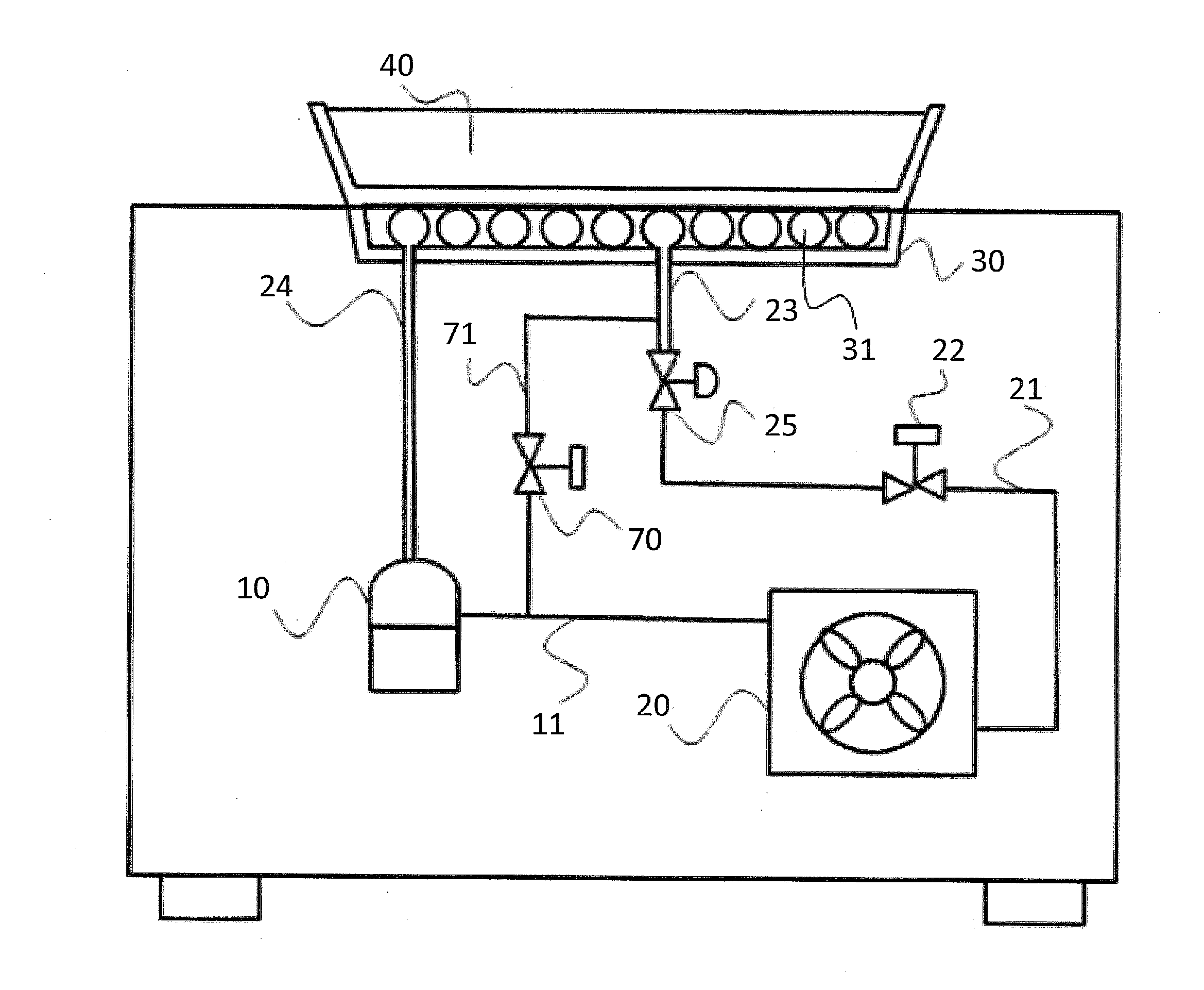
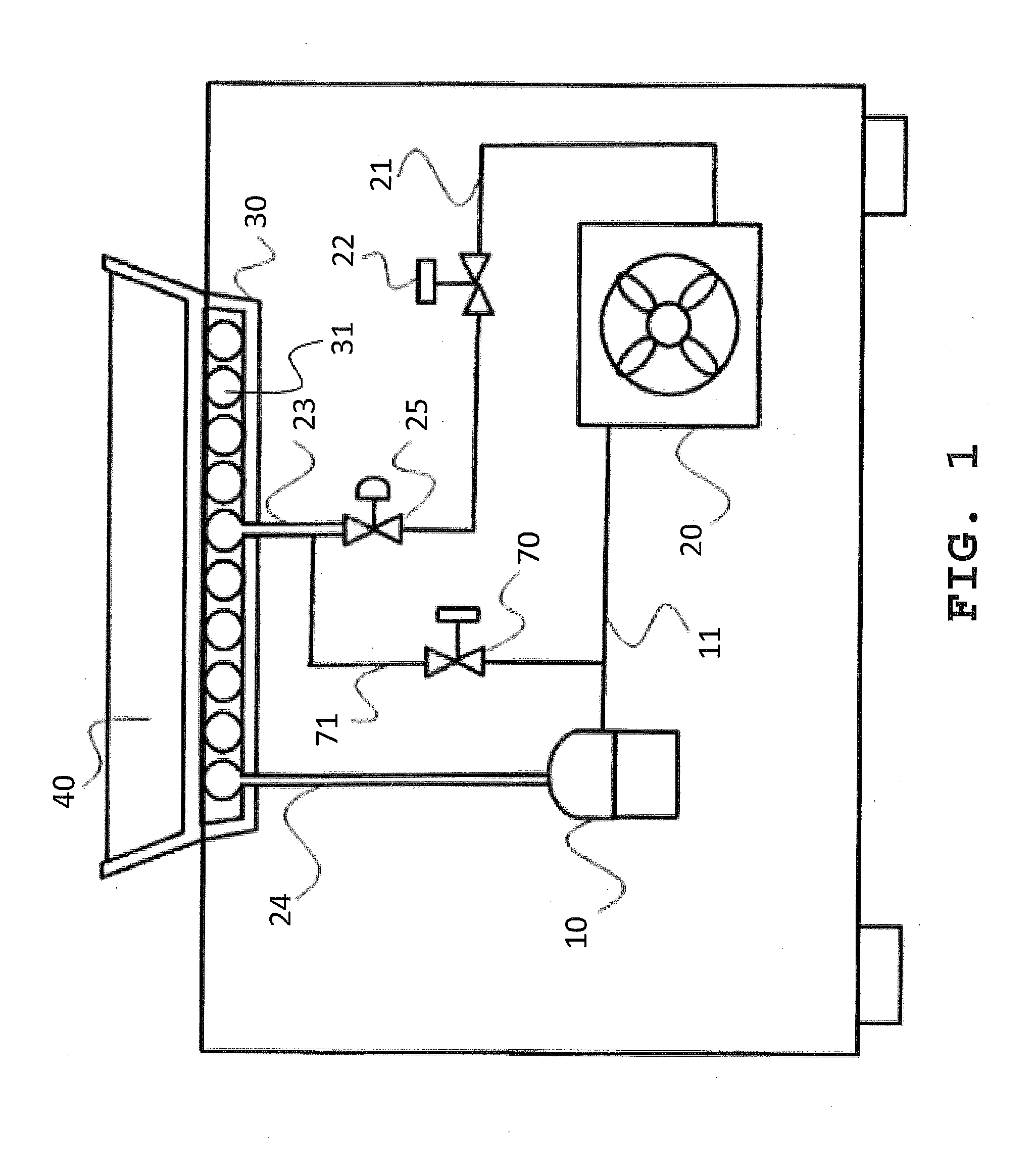
[0022]FIG. 1 shows a conventional ice making apparatus. The apparatus includes a first discharging tube 11 connecting the compressor 10 to the condenser 20, the second discharging tube 21 connecting the condenser 20 to the expansion valve 22 and an inlet tube 23 connecting the expansion valve 22 and the evaporator 30. The bypass line 71 connects the first discharging tube 11 and the inlet tube 23 and the switching means 70 is installed in the middle of the bypass line 71. An additional switching means 25 is installed in the middle of the inlet tube. There is no separator to collect liquefied refrigerant from the pipe which connects the evaporator 30 to the compressor 10, and the coolant pipe 31 is configured to have a coil from the inlet tube 23 to the outlet tube 24.

[0023]In the freezing mode, refrigerant flows from the compressor 10 to the condenser 20, to the expansion valve 22, to the evaporator 30, and then back to the compressor 10. But, in the heating mode when the switching ...


PUM


Abstract

This invention relates to a portable onsite ice making apparatus having a bypass tube, which includes a compressor equipped with a condenser having heat removal capacity of about 2,400˜2,600 BTU / hr; an expansion valve; an evaporator being in heat exchange relationship with an ice making tray; a bypass tube for the refrigerant to bypass the condenser and the expansion valve; and a switching means selectively changing the flow of the refrigerant from the compressor to the condenser or from the compressor to the bypass tube. The portable ice making apparatus has heat removal capacity to cool the ice making tray to −27° C.˜−26° C. within 3 minutes and heating capacity to heat the ice making tray from about −27° C.˜−26° C. to about 50° C.˜−60° C. within 30 seconds. The area of the capillary tube in the bypass tube to the area of the first discharging tube is about 1 / 25˜ 1 / 10.

Description

FIELD OF THE INVENTION[0001]The invention relates to a portable ice making apparatus having a bypass tube and more particularly to a portable onsite ice making apparatus having a bypass tube to switch between freezing and heating modes for quickly manufacturing ice products such as ice creams, sherbets, or ice cakes.BACKGROUND OF THE INVENTION[0002]A variety of ice making apparatuses have been proposed and disclosed and, among such apparatuses, a particular ice making apparatus was introduced so that ices can be manufactured onsite to meet the need of a customer for sherbets, ice creams or ice cakes.[0003]A conventional apparatus for manufacturing ice via rapid ice facture and rapid ice thaw was proposed, as described in FIG. 1 and disclosed in the PCT / KR2005 / 001365. Such apparatus controls the thawing process through a bypass line so that the flow of refrigerant can by-pass the condenser without having to go though the normal process of ice making through the condenser. The bypass ...

Claims


Application Information

Patent Timeline
Patent Type & Authority Applications(United States)
IPC IPC(8): F25C5/08
CPCF25C5/08F25B47/022F25C5/10F25B2400/0403F25B2400/0411F25B2500/01F25C2700/12
Inventor SUL, DONG HWAN
Owner SUL DONG HWAN
Why Eureka
Try Eureka