Pneumatic tire for heavy load

a pneumatic tire and heavy load technology, applied in the field of pneumatic tires, can solve the problems of ptl1 not being able to achieve satisfactory reduction of rolling resistance, affecting fuel efficiency, and rib-pattern tires, and achieve good performance in both fuel efficiency and drainag

Inactive Publication Date: 2014-08-28
BRIDGESTONE CORP
View PDF7 Cites 28 Cited by
  • Summary
  • Abstract
  • Description
  • Claims
  • Application Information

AI Technical Summary

Benefits of technology

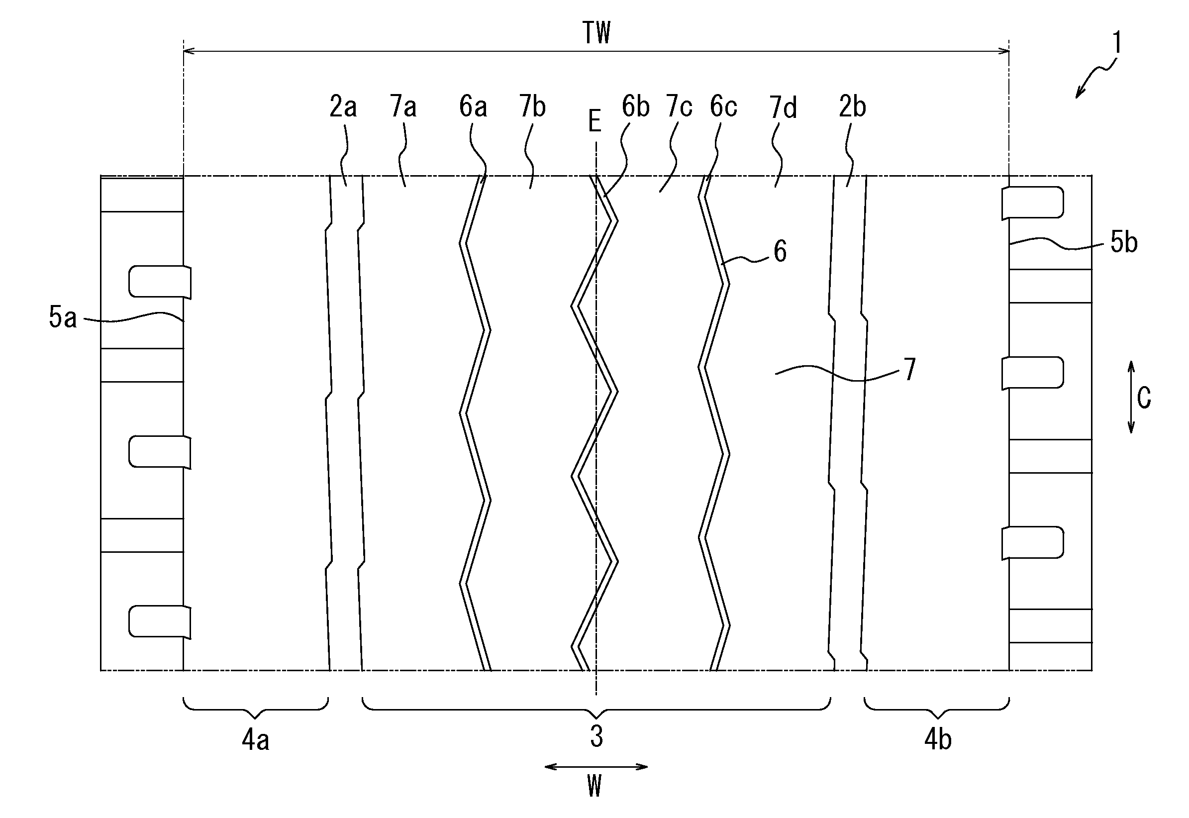
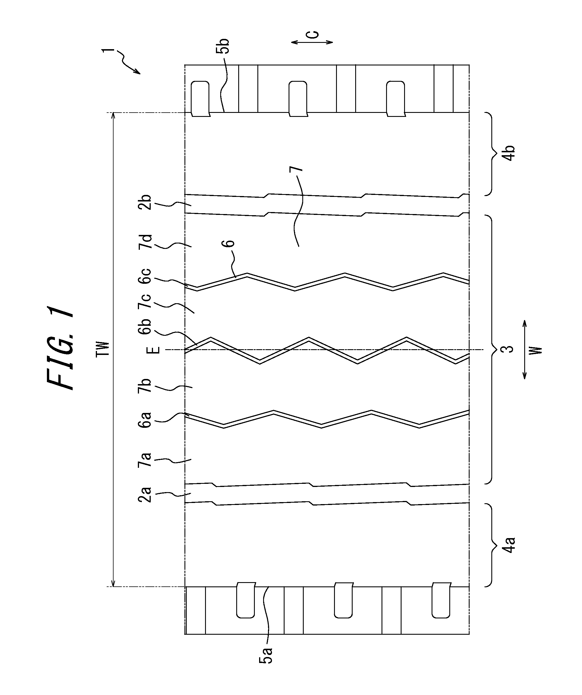
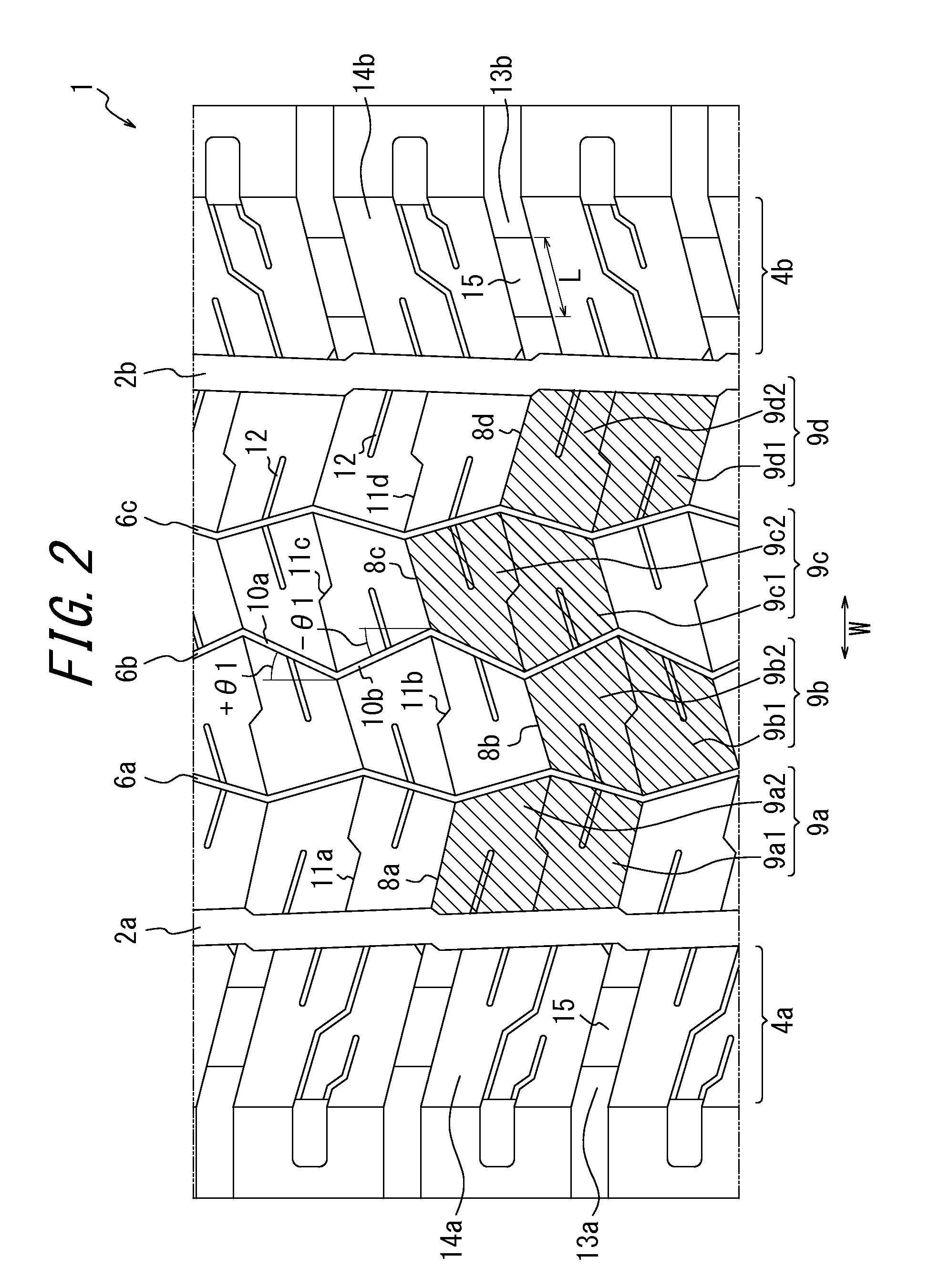
[0016]According to the present invention, it is possible to provide a tire for use in a heavy load vehicle such as a truck, a bus and the like, which tire exhibits good performances in both fuel efficiency and drainage by appropriately demarcation of land portions located in the central region of a ground contact surface of a tread portion of the tire by various types of narrow (fine) grooves.

Problems solved by technology

On the other hand, the rib-pattern tire has a problem in that it cannot satisfactorily reduce rolling resistance affecting fuel efficiency, after all, because the rib-like land portions demarcated by wide circumferential main grooves exhibit relatively large magnitudes of deformation when a force is inputted in the tire width direction in a cornering situation or the like, although the rib-like land portions extending integrally and continuously in the circumferential direction exhibit relatively high rigidity against a force inputted in the circumferential direction in a driving / braking situation and can suppress magnitudes of deformation thereof in the circumferential direction relatively well.
PTL1 therefore cannot cause an effect of reducing rolling resistance in a satisfactory manner, thus leaving room for further improvement.
However, the tire has a problem in that it exhibits relatively high rolling resistance because the block-like land portions thereof adjacent to each other with the circumferential main grooves and the width direction main grooves therebetween fail to be brought into contact with each other when these land portions are in contact with the ground, whereby rigidity of the tread land portion fully depends on respective rigidities of the individual block land portions, which are each relatively small, and magnitudes of deformation of the land portions become significantly high after all.

Method used


Image

  • Pneumatic tire for heavy load
  • Pneumatic tire for heavy load
  • Pneumatic tire for heavy load

Examples


examples

[0044]Next, pneumatic test tires for heavy load according to the present invention were prepared and performances thereof were evaluated, as described below. Test tires of Examples 1 to 5 each had tire size: 315 / 70R22.5 and characteristics details of the structure of a tread portion as shown in Table 1. Tire structures other than the structure of the tread portion of Examples 1-5 tires were the same as those of the conventional pneumatic tire for heavy load because the unique characteristics of the present invention lie in a tread pattern. A test tire having tire size: 315 / 70R22.5 and a tread pattern as shown in FIG. 8 was also prepared as Conventional tire for comparison.

[0045]Table 1

TABLE 1TirewidthCircumferentialCircumferentialdirectionTire widthBlock-mainnarrow groove 6finedirection mainlike sidegroove 2Configurationgroove 8groove 13Bottom-raisedlandGrooveGrooveinGrooveGrooveGrooveportion 15portionwidthwidthextendingwidthwidthdepthLengthHeightWidth(mm)(mm)direction(mm)(mm)(mm)L ...


PUM


Abstract

An object of the present invention is to provide a tire for heavy load, which exhibits good performances in both fuel efficiency and drainage. One example of the pneumatic tire comprising a tread portion and a pair of circumferential main grooves formed in a ground contact surface of the tread portion to section the ground contact surface of the tread portion into the central region and respective side regions, wherein the tire further comprises three circumferential narrow grooves formed in the central region to demarcate four rib-like center land portions in the central region; and the central region has a structure in which openings of the circumferential narrow grooves are closed so that the rib-like center land portions adjacent to each other with the circumferential narrow grooves therebetween are in contact with and thus supported by each other when the tire is in contact with the ground.

Description

TECHNICAL FIELD[0001]The present invention relates to a tire for use in a heavy-load vehicle such as a truck, a bus and the like, which tire exhibits good performances in both fuel efficiency and drainage.BACKGROUND ART[0002]General examples of a pneumatic tire for heavy load for use in a heavy-load vehicle such as a truck, a bus and the like include: a what is called “rib-pattern” tire, in which plural circumferential grooves extending in the tire circumferential direction are formed in a ground contact surface of a tread to demarcate a plurality of rib-like land portions in the tread, as shown in FIG. 8; and a what is called “block-pattern” tire, in which plural circumferential grooves extending in the tire circumferential direction and plural width direction grooves extending in the tire width direction are formed in a ground contact surface of a tread to demarcate a plurality of block land portions in the tread.[0003]With regard to a tire having a rib-pattern, the tire has a rel...

Claims


Application Information

Patent Timeline
Patent Type & Authority Applications(United States)
IPC IPC(8): B60C11/03
CPCB60C11/0309B60C2011/0348B60C2011/0386B60C2011/0346B60C2200/06B60C11/0306B60C11/1236
Inventor HAGA, TAKAFUMI
Owner BRIDGESTONE CORP
Why Eureka
Try Eureka