Rotating pumping apparatus with seal mechanism

Active Publication Date: 2014-08-28
ADVICS CO LTD
View PDF17 Cites 6 Cited by
  • Summary
  • Abstract
  • Description
  • Claims
  • Application Information

AI Technical Summary

Benefits of technology

The patent text describes an improved structure for a rotating pumping apparatus that reduces the leakage of grease between parts. The apparatus includes a sealing member and an oil seal that work together as a double seal mechanism to prevent fluid leakage. When there is a leak, the oil seal blocks the fluid from leaking, and the fluid is returned back to the chamber where it originated to avoid leakage. The apparatus also includes a labyrinthine flow path that helps keep lubricating grease in place without allowing it to flow into the chamber where the fluid is returned. Overall, this design improves the efficiency and lifespan of the pumping apparatus.

Problems solved by technology

There is, however, a possibility that grease between the oil seal and the shaft may leak following the brake fluid returning from the chamber between the sealing assembly and the oil seal toward the pump and then enter a brake fluid circuit.
Particularly, in the case where the rotating pump primes the brake fluid and supplies it to a wheel cylinder to elevate the pressure in the wheel cylinder, the rotating pump needs to be operated for a long time, thus increasing the possibility of leakage of the grease into the brake fluid circuit.

Method used


Image

  • Rotating pumping apparatus with seal mechanism
  • Rotating pumping apparatus with seal mechanism
  • Rotating pumping apparatus with seal mechanism

Examples


first embodiment

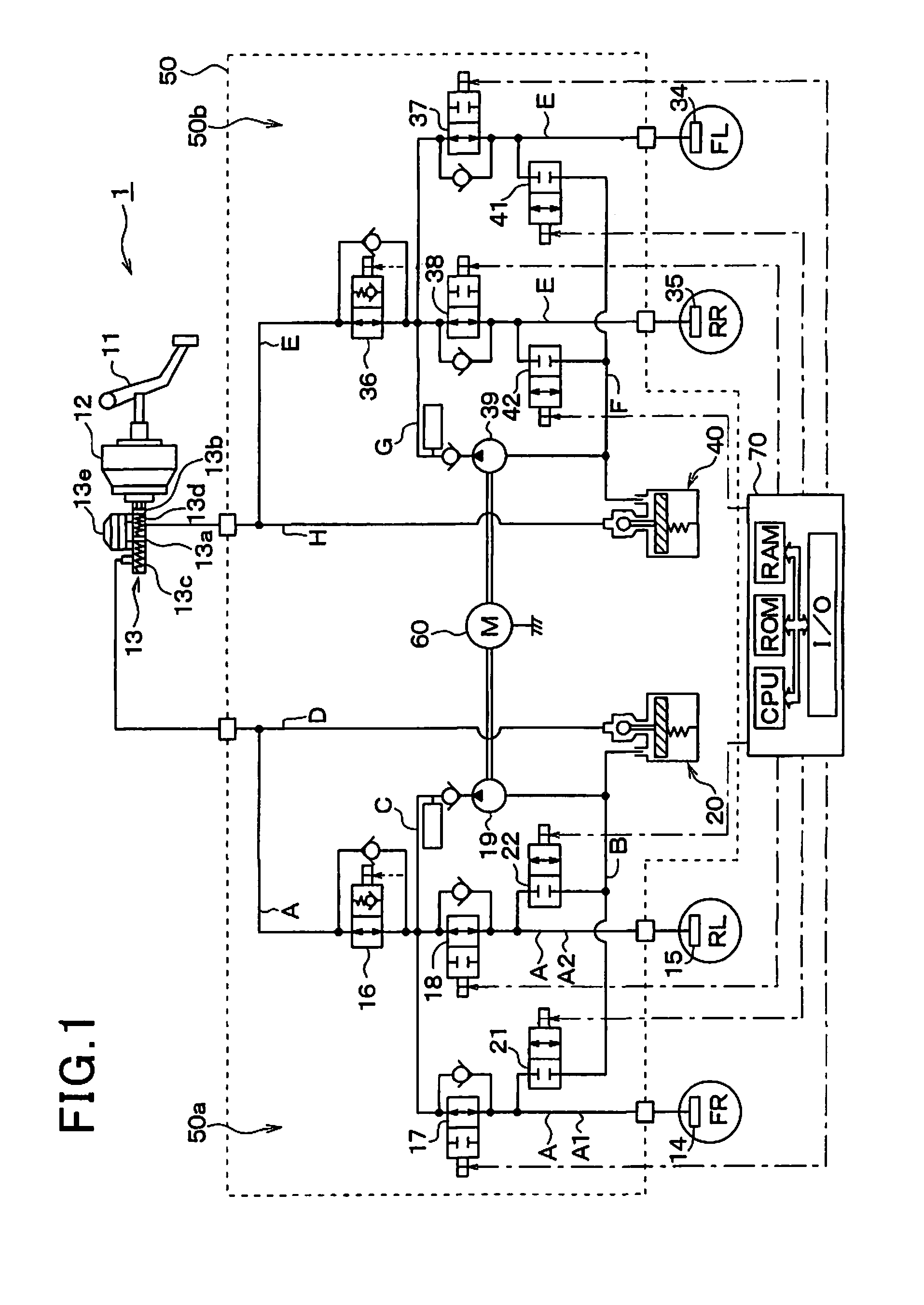
[0032]Referring to FIG. 1, there is shown an automotive brake system equipped with a rotating pumping apparatus according to the first embodiment of the invention. The brake system, as referred to herein, is used with a front-wheel-drive vehicle equipped with a so-called diagonal split system which includes two brake hydraulic circuits one of which controls the right front and the left rear wheel and the other of which controls the left front and the right rear wheel, but may be used with a front / rear split system.

[0033]The brake system includes a brake device 1 which is equipped with a brake pedal 11 (i.e., a brake actuating member) to be depressed by a vehicle occupant or driver for applying the brakes to the vehicle, a brake booster 12, a master cylinder 13, wheel cylinders 14, 15, 34, and 35, and a brake pressure control actuator 50. The actuator 50 has a brake ECU (Electronic Control Unit) 70 installed therein. The brake ECU 70 works to control the braking force, as developed b...

second embodiment

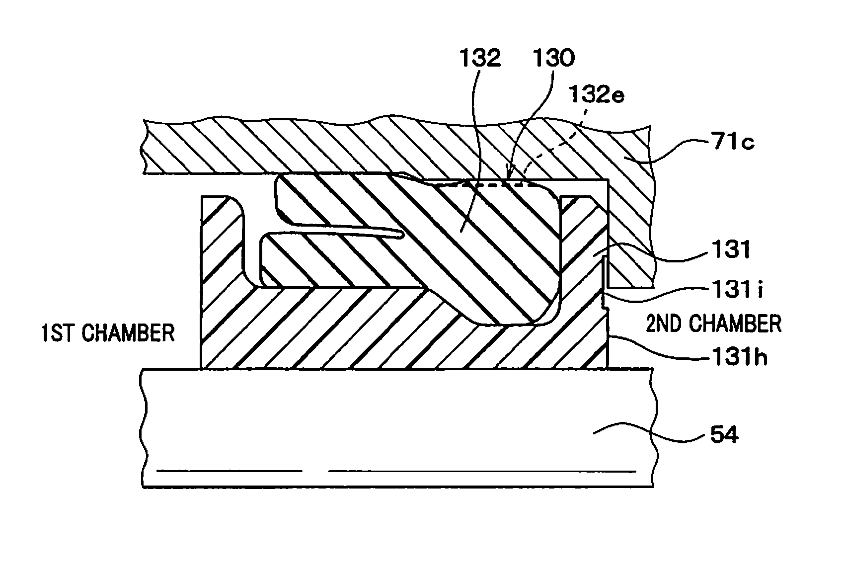
[0108]The second embodiment will be described below which is different only in layout of the hydraulic grooves 131i of the pump body 100 from the first embodiment. Other arrangements of the pump body 100 are identical with those in the first embodiment, and explanation thereof in detail will be omitted here.

[0109]The resinous ring 131, as illustrated in FIG. 8, has formed in the end surface 131h facing the oil seal 140 two hydraulic grooves 131i which are identical in structure with those in the first embodiment. The hydraulic grooves 131i are diametrically opposed to each other, that is, located at an interval of 180° away from each other in the circumferential direction of the resinous ring 131.

[0110]Use of the two hydraulic grooves 131i provides the same beneficial advantages as described in the first embodiment, but the alignment of the outer end of one of the hydraulic grooves 131i which opens on the outer periphery of the resinous ring 131 with one of the slits 132e in the rad...

third embodiment

[0112]The third embodiment will be described below which is different only in configuration of the hydraulic grooves 131i of the pump body 100 from the first embodiment. Other arrangements of the pump body 100 are identical with those in the first embodiment, and explanation thereof in detail will be omitted here.

[0113]The resinous ring 131 has formed in the end surface 131h facing the oil seal 140 four hydraulic grooves 131i each of which extends straight from the center hole (i.e., the inner space) of the resinous ring 131 to the outer periphery (i.e., an outer circumferential surface) of the resinous ring 131 in the radial direction of the resinous ring 131 (i.e., the seal ring 130). The hydraulic grooves 131i are arranged at a regular or equal interval away from each other in the circumferential direction of the resinous ring 131. Each of the outer ends of the hydraulic grooves 131i which opens on the outer periphery of the resinous ring 131 is misaligned with, that is, offset f...


PUM


Abstract

A rotating pumping apparatus is provided which may be employed in an automotive brake system. The rotating pumping apparatus includes a sealing member and an oil seal which are disposed around a pump drive shaft, and lubricating grease disposed between the oil seal and the pump drive shaft. The sealing member is made up of a resinous ring and a rubber cup. The sealing member has formed therein a labyrinthine flow path which extends from the resinous ring to the rubber cup. The labyrinthine flow path is designed to permit fluid to flow therethrough and create the resistance to flow of the lubricating grease to avoid leakage of the grease outside the sealing member.

Description

CROSS REFERENCE TO RELATED DOCUMENT[0001]The present application claims the benefit of priority of Japanese Patent Application No. 2013-33365 filed on Feb. 22, 2013, the disclosure of which is incorporated herein by reference.BACKGROUND OF THE INVENTION[0002]1. Technical Field of the Invention[0003]This disclosure relates generally to a rotating pumping apparatus with a sealing mechanism in which a sealing member made of up a resinous ring and a rubber ring is disposed in a clearance between a pump housing and a shaft extending in the pump housing, and the resinous ring is placed in close contact with the shaft to create a hermetic seal.[0004]2. Background Art[0005]Japanese Patent First Publication No. 2012-063003 teaches a rotating pump with a sealing assembly for creating a hermetical seal between a housing and a shaft disposed inside the housing. The sealing assembly is made up of a resinous ring and a rubber ring. The rubber ring is disposed outside the resinous ring and works t...

Claims


Application Information

Patent Timeline
IPC IPC(8): F16J15/32B60T17/00F04C15/00
CPCF16J15/3204F16J15/002B60T17/02
Inventor HISADA, YOSHITAKEFUCHIDA, TAKESHI
Owner ADVICS CO LTD
Why Eureka
Try Eureka