
Photovoltaic power generation system, control method and control program for photovoltaic power generation system

a photovoltaic power generation and photovoltaic technology, applied in the direction of dc source parallel operation, emergency power supply arrangement, transportation and packaging, etc., can solve the problems of difficult to count the availability the likely impact of the pv power generation system, and the difficulty of counting the power sour

Inactive Publication Date: 2014-08-28
KK TOSHIBA
View PDF6 Cites 35 Cited by
  • Summary
  • Abstract
  • Description
  • Claims
  • Application Information

AI Technical Summary

Benefits of technology

The patent text describes a system for generating PV power, which includes a PV power generator and a PV inverter. The ratio of the output of the PV power generator to the output of the PV inverter is set to be 140% or higher. This design ensures that excess PV power is utilized efficiently by reducing the likelihood of power loss during transmission. A method and program for implementing this system are also provided. The technical effect is a more efficient and reliable PV power generation system.

Problems solved by technology

However, the output by the PV power generation system is likely to be affected by weather, and is unstable in comparison with the output by conventional power generation facilities.
Accordingly, it is often difficult to count the availability of the PV power generation system as a stable power source relative to a demand to a power grid connected with the PV power generation system.
It is difficult to count a power source in an operation plan which is capable of supplying power at a given time but which frequently becomes unable to supply power at another given time within a short time period.
In this case, in a power grid connected with the PV power generation system, the power demand and the power supply become unbalanced, and thus it becomes sometimes difficult to maintain a frequency at constant.

Method used


Image

  • Photovoltaic power generation system, control method and control program for photovoltaic power generation system
  • Photovoltaic power generation system, control method and control program for photovoltaic power generation system
  • Photovoltaic power generation system, control method and control program for photovoltaic power generation system

Examples


first embodiment

A. First Embodiment

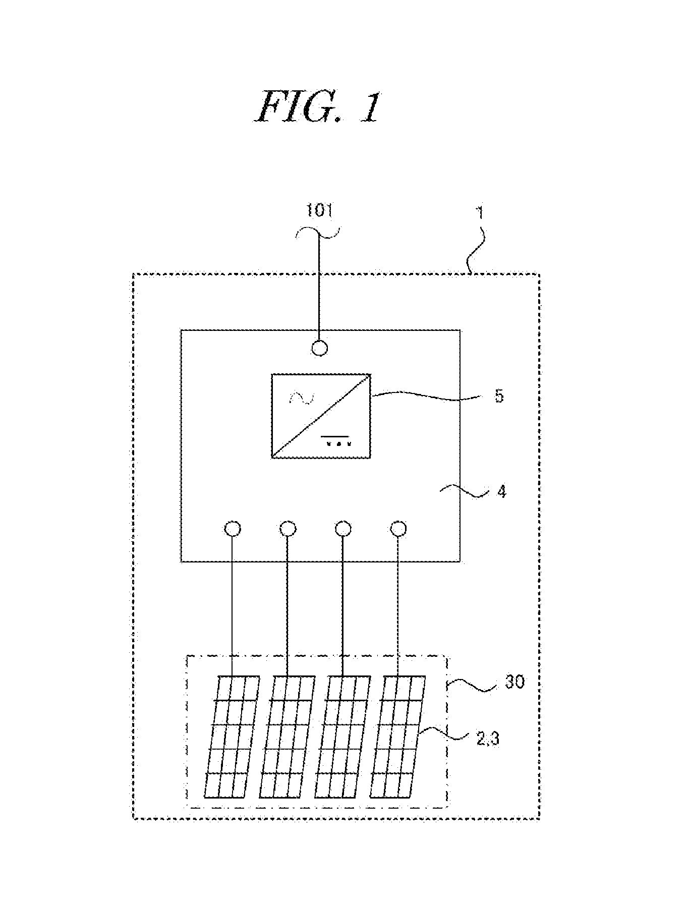
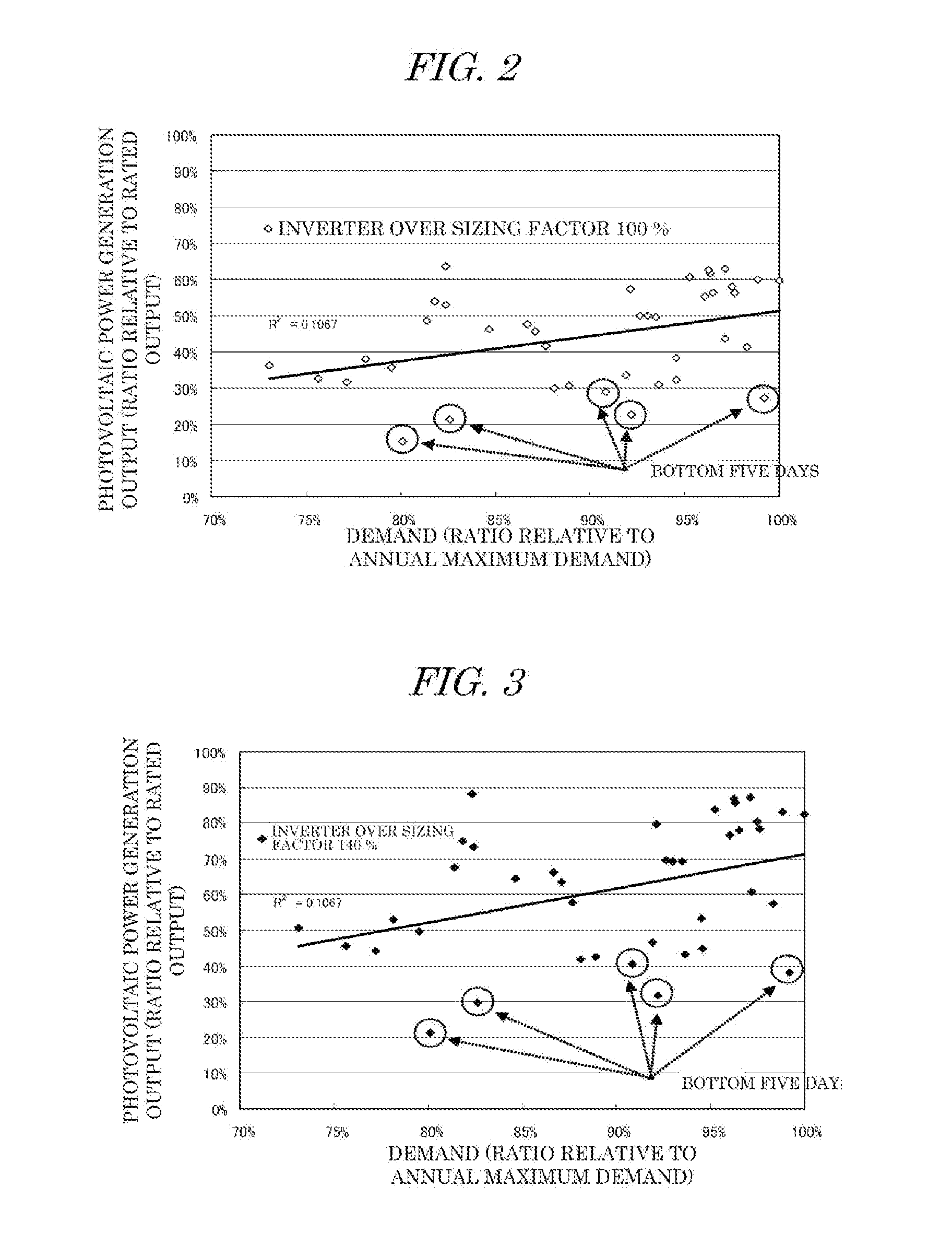
[0025]A photovoltaic(PV) power generation system of this embodiment will be explained with reference to FIGS. 1 to 4.

[0026][1. Configuration]

[0027][1-1. Basic Configuration]

[0028]A photovoltaic(PV) power generation system 1 of this embodiment includes PV strings 3, and a PV inverter 4. The PV strings 3 have multiple PV modules 2 connected in series. The multiple PV strings 3 are connected in parallel with the PV inverter 4. In the following explanation, the multiple PV strings 3 connected with the PV inverter 4 will be collectively referred to as a PV power generator 30.

[0029]The PV inverter 4 is connected between the PV strings 3 and a power grid 101, and connects the PV strings 3 to the power grid 101. The PV inverter 4 includes an inverter 5. The inverter 5 is a converter that converts DC power output by the PV power generator 30 into AC power with a predetermined frequency. An example predetermined frequency is a commercial power frequency when the power grid ...

second embodiment

B. Second Embodiment

[0054][1. Configuration]

[0055]Next, an explanation will be given of a second embodiment with reference to FIGS. 5 and 6. The same configuration as that of the first embodiment will be denoted by the same reference numeral, and the duplicated explanation thereof will be omitted.

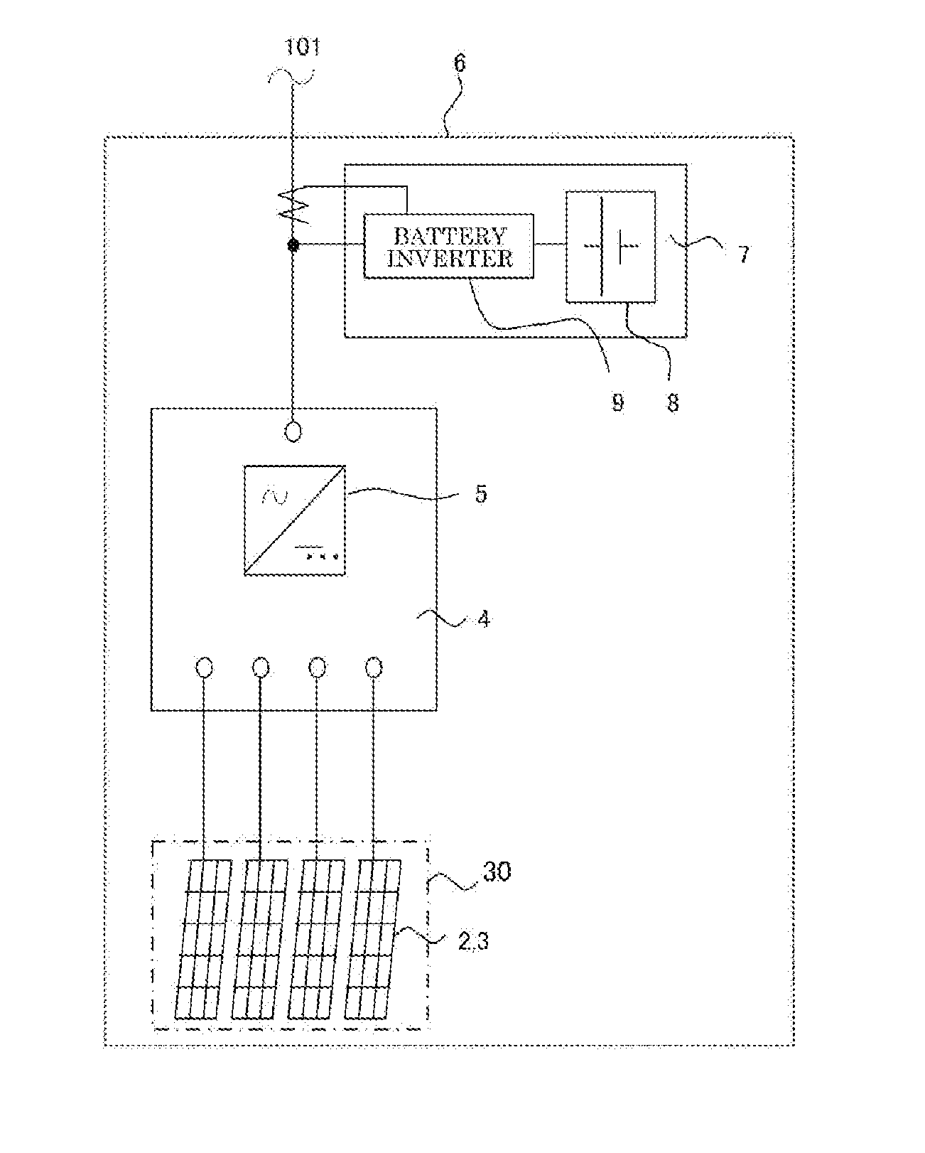
[0056]As illustrated in FIG. 5, this embodiment is constructed as a battery-equipped PV power generation system 6. That is, a battery system 7 is added to the AC system end of the PV power generation system 1 indicated in the first embodiment.

[0057]The battery system 7 includes a battery 8, and a battery inverter 9. A secondary battery that can perform charging and discharging may be used as the battery 8. For example, a lead battery, a lithium-ion battery, nickel and hydrogen batteries are applicable as the battery 8.

[0058]The battery inverter 9 converts the power output by the battery 8 into AC power with a predetermined frequency, and outputs the AC power to the power grid 101. When, for...

third embodiment

C. Third Embodiment

[0067][1. Configuration]

[0068]Next, an explanation will be given of a third embodiment with reference to FIGS. 7 and 8. Note that the same configuration as that of the first embodiment will be denoted by the same reference numeral, and the duplicated explanation will be omitted.

[0069]As explained above, the PV inverter 4 includes an MPPT control function. That is, since the output by the PV power generator 30 changes in accordance with a solar irradiation intensity and the surface temperature of the PV module 2, the operating point is changed so as to track the maximum output point, thereby obtaining the maximum power.

[0070]The MPPT control is, more specifically, carried out by the controller of the PV inverter 4 as follows upon monitoring the current and the voltage. First, the controller slightly changes a DC operating voltage or a DC current, or, both DC operating voltage and DC current for each predetermined time cycle.

[0071]The controller compares the output ...


PUM


Abstract

A photovoltaic power generation system includes a photovoltaic power generator including a plurality of PV modules, and a PV inverter that connects an output by the photovoltaic power generator to a power grid. The ratio of a rated output by the photovoltaic power generator defined by a rated output by the PV modules relative to a rated output by the PV inverter is equal to or greater than 140%. The photovoltaic power generation system further includes a battery unit, a battery inverter that connects an output by the battery unit to a power grid, and a controller that adjusts an output by the battery unit in such a way that an output by the battery inverter becomes equal to or greater than a preset electric power together with an output by the PV inverter.

Description

CROSS-REFERENCE TO RELATED APPLICATIONS[0001]This application is based upon and claims the benefit of priority from Japan Patent Application No. 2013-033896, filed on Feb. 22, 2013, the entire contents of which are incorporated herein by reference.BACKGROUND OF THE INVENTION[0002]1. Field of the Invention[0003]The present disclosure relates to a photovoltaic(PV) power generation system including a PV module and a PV inverter, and a control method and a control program for the PV power generation system.[0004]2. Description of the Related Art[0005]PV power generation systems are configured to obtain desired power by connecting an output by a PV module to a device called a PV inverter (PCS). In general, such PV power generation systems include multiple PV strings connected in series relative to the PV module and connected in parallel with the PV inverter.[0006]The PV inverter has an inverter function for a connection with a power grid. The inverter function converts DC power output by...

Claims


Application Information

Patent Timeline
Patent Type & Authority Applications(United States)
IPC IPC(8): H02J9/06
CPCH02J9/061H02J3/32H02J7/35H02J2300/26H02J2300/24H02J3/381Y02E10/56
Inventor ARAI, KAZUTONIIMOTO, TAKESHI
Owner KK TOSHIBA
Learn More