Power factor correction converter with current regulated output

a technology of power factor correction and converter, which is applied in the direction of electric discharge tubes, discharge tubes/lamp details, basic electric elements, etc., can solve the problems of increased cost of led string connection, and increased cost of manufacturing led lighting devices. , to achieve the effect of shortening the duty cycl

Active Publication Date: 2014-08-28
ASAHI KASEI ELECTRONICS CO LTD
View PDF1 Cites 35 Cited by
  • Summary
  • Abstract
  • Description
  • Claims
  • Application Information

AI Technical Summary

Benefits of technology

[0068]In some embodiments, if the second level voltage is less than the reference voltage, the EA amplifies its output via the multiplier, and the PWM comparator extends the duty cycle to boost the first level voltage; or if the second level voltage is greater than the reference

Problems solved by technology

However, the cost of manufacturing LED lighting devices is still much higher than the traditional incandescent and fluorescent bulbs and therefore, becomes an obstacle to the migration.
However, in this prior art configuration, the AC current does not necessarily follow the AC voltage so as to achieve a high Power Factor level >0.9.
However, in EP 2315497A1, the LED string cannot be connect

Method used


Image

  • Power factor correction converter with current regulated output
  • Power factor correction converter with current regulated output
  • Power factor correction converter with current regulated output

Examples


exemplary embodiment 500

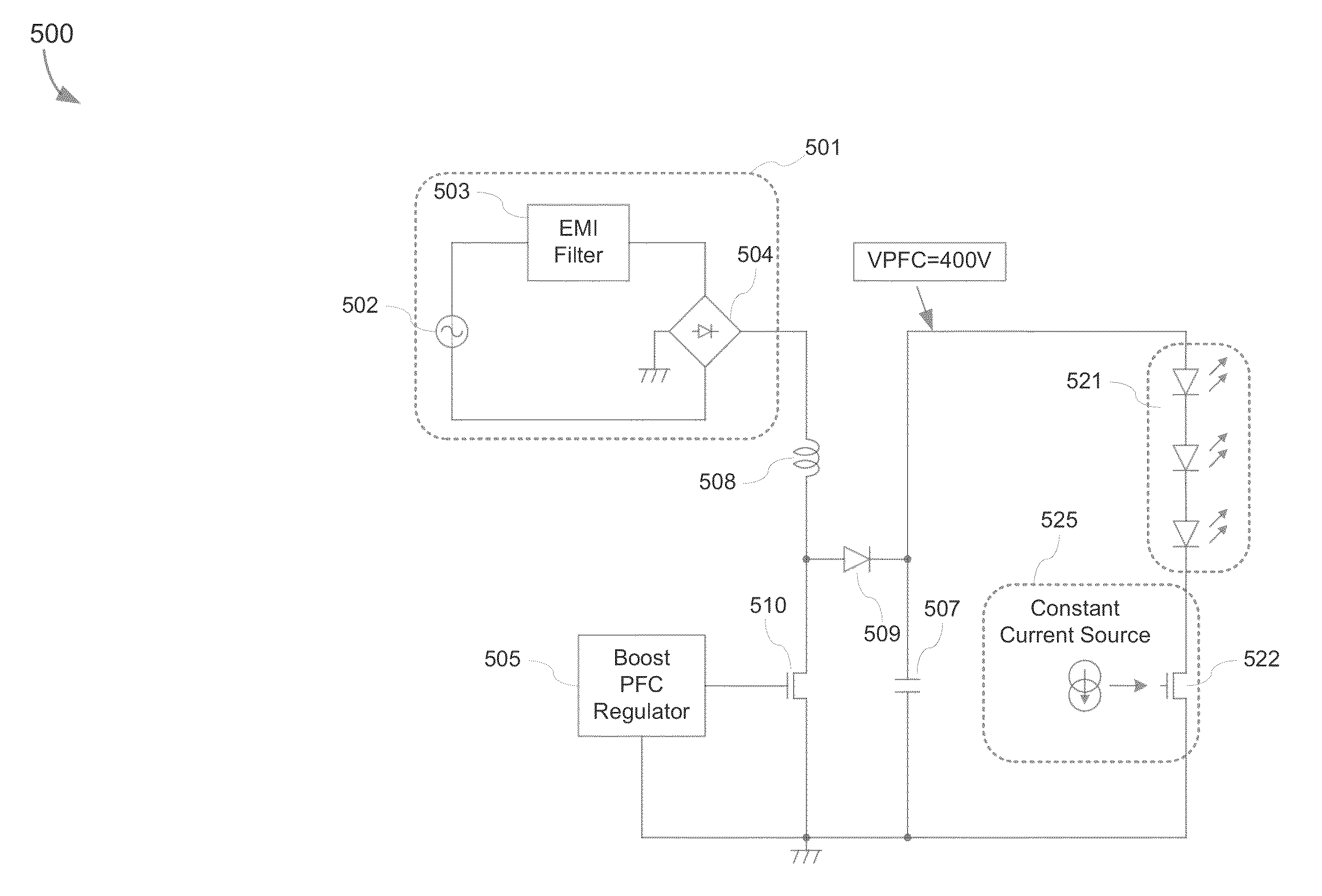
[0089]FIG. 5 is an exemplary embodiment 500 of a power factor correction (PFC) converter in a boost configuration in accordance with the present invention. The exemplary embodiment 500 may comprise a set-up circuit 501, a boost PFC regulator 505, a coil 508, a transistor 510, a diode 509, a capacitor 507, an LED string comprising a plurality of LEDs connected in series and a constant current source 525. The set-up circuit may further comprise an AC source, an electromagnetic interference (EMI) filter and a diode bridge 504. A high DC level of 400v, i.e., VPFC level is outputted to the anode of the LED string. However, as each LED has approximate 3v voltage drop at a room temperature, the exemplary embodiment 500 requires a large number of LEDs to be used in order to achieve high efficiency. Fewer diodes used in the LED string would lead to extra voltage drop across the constant current source which means less efficiency.

[0090]FIG. 6 is an exemplary embodiment of a power factor corre...

exemplary embodiment 600

[0092]FIG. 7 is an exemplary embodiment of a power factor correction (PFC) converter in a boost configuration followed by a buck regulator as illustrated in exemplary embodiment 600 with detailed configuration of a boost PFC regulator, a buck regulator and a low-side connected load in accordance with the present invention. In the exemplary embodiments 700, the boost PFC regulator 705 may further comprise a first pair of resistor dividers 741, a second pair of resistor dividers 742, a first reference voltage 745 corresponding to the first level voltage v1 at the output of a first diode 709, a first error amplifier (EA) 746, a multiplier 747, a first oscillator 744 and a first pulse width modulation (PWM) comparator 748. An AC voltage from the set-up circuit 701 may be inputted to the boost PFC regulator 705 via the first pair of resistor dividers 741. The divided voltage may be applied to the multiplier 747 as one input. The first EA 746 may receive the first level voltage v1 via the...

exemplary embodiment 800

[0096]In any one of the exemplary embodiment 700 and the exemplary embodiment 800, when the first transistor 710 is on, the first coil 708 accumulates received current, and when the first transistor 710 is off, the first coil 708 transmits accumulated current and outputs the first level voltage v1 to the buck converter 711 via the first diode 709. Such first level voltage v1 is about 400v in order to cover the Universal AC line input range, and therefore achieve a high PFC by allowing AC current to follow the AC line envelope.

[0097]In any one of the exemplary embodiment 700 and the exemplary embodiment 800, the boost PFC regulator 705 may be configured to achieve a high power factor correction level by regulating the first time pattern of the on / off status of the first transistor 710 in order to force the AC current to follow the AC voltage to achieve a high PFC level. The high power factor correction level that can be achieved is approximately equal to 0.96 or is greater than 0.96,...


PUM


Abstract

A power factor correction converter in a buck-boost configuration may include a set-up circuit configured to supply an input voltage, a buck transistor connected to the set-up circuit, and configured to receive a current from the diode bridge, a first diode connected to the buck transistor, a boost transistor, a resistor connected to the boost transistor, a coil that connects the buck transistor and the boost transistor, a buck-boost PFC regulator connected to the set-up circuit, and configured to regulate a time pattern of the on/off status of the first transistor and the second transistor synchronously, a second diode connected to the coil and the boost transistor, and configured to output a first level voltage, a capacitor connected to the second diode and a load connected to the second diode.

Description

FIELD OF INVENTION[0001]The present invention relates generally to a light emitting diode (LED) lighting system in the industrial / home lighting field, and in particular, relates to a power factor correction (PFC) converter with current regulated output implemented in an LED lighting system in the industrial / home lighting field.BACKGROUND OF INVENTION[0002]The LED device has matured greatly since the time of its inception over thirty years ago. The semiconductor technology enables an LED lighting device with orders of magnitude longer life than the traditional incandescent and fluorescent bulbs. To save energy and stop global warming, world-wide governments propose migrating away from the traditional incandescent and fluorescent bulbs. However, the cost of manufacturing LED lighting devices is still much higher than the traditional incandescent and fluorescent bulbs and therefore, becomes an obstacle to the migration. While the manufacturing cost of the LED lighting devices remains h...

Claims


Application Information

Patent Timeline
IPC IPC(8): H05B37/02
CPCH05B37/02H05B45/3725Y02B20/30
Inventor MARTIN-LOPEZ, FERNANDO RAMONGAVRILA, GABRIEL C.UMEKI, TAKAHIRO
Owner ASAHI KASEI ELECTRONICS CO LTD
Why Eureka
Try Eureka