
Power factor correction circuits

a technology of power factor and correction circuit, which is applied in the direction of electric variable regulation, process and machine control, instruments, etc., can solve the problems of inconvenient transportation

Inactive Publication Date: 2008-01-31
BENQ CORP
View PDF3 Cites 12 Cited by
  • Summary
  • Abstract
  • Description
  • Claims
  • Application Information

AI Technical Summary

Benefits of technology

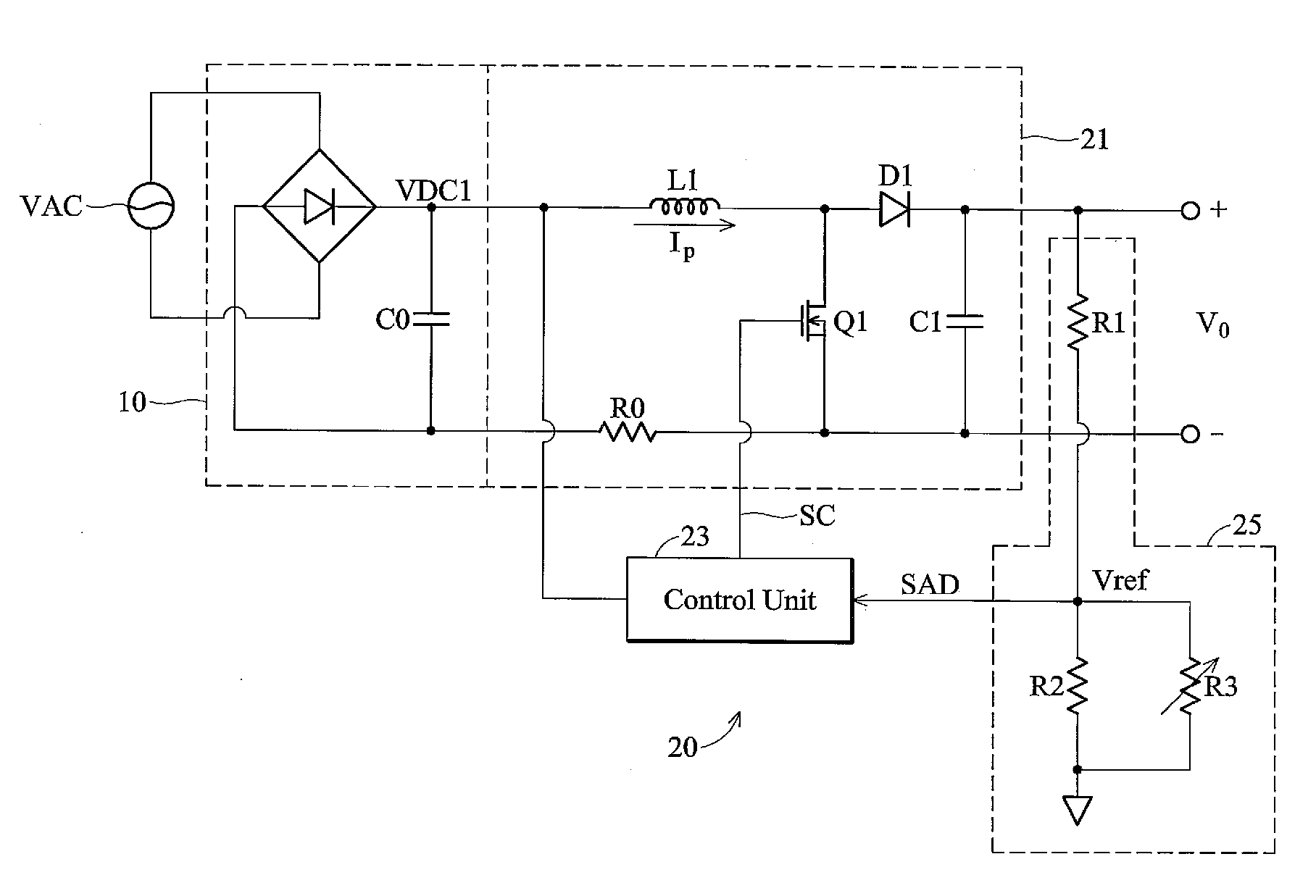
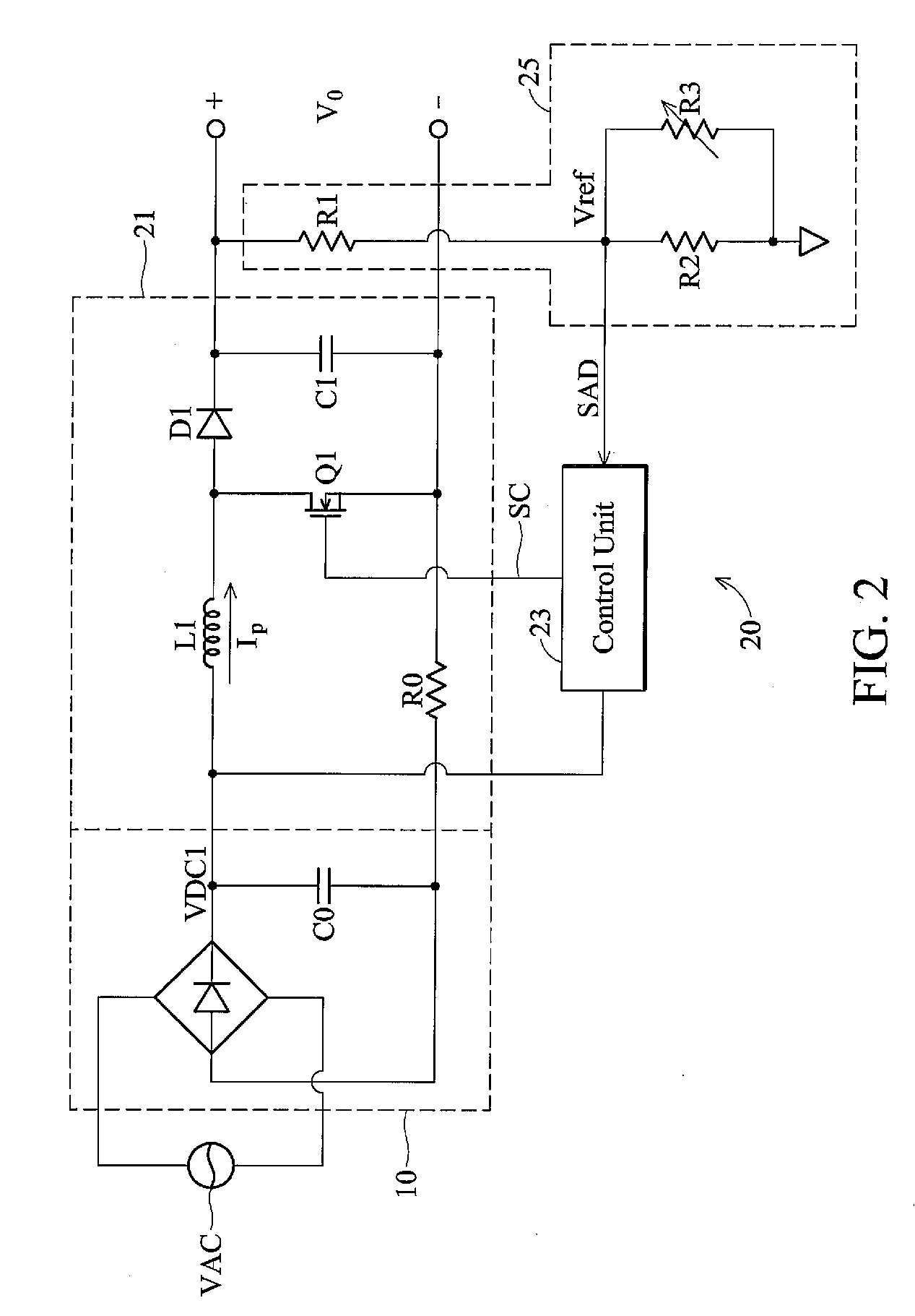
[0007]The invention provides another embodiment of a power factor correction circuit, in which a boosting converter comprises a switching element and an inductor, to convert a rectified voltage into a DC output voltage according to a formula ofVo=1(1-D(t))×V(t).V(t) represents the rectified voltage, Vo represents the DC output voltage and D(t) represents a duty cycle of the switching element. A voltage division circuit comprises a thermister with positive temperature coefficient, to generate an adjustment signal according to a present temperature and the DC output voltage. A control unit shortens the duty cycle of the switching element thereby lowering the DC output voltage when the temperature of the switching element or the inductor increases, according to the adjustment signal.

Problems solved by technology

Conventional display apparatus, such as cathode-ray tube (CRT) or liquid crystal displays (LCD), can only provide an image up to 30 40 inches wide and are inconvenient to transport.

Method used


Image

  • Power factor correction circuits
  • Power factor correction circuits
  • Power factor correction circuits

Examples


Embodiment Construction

[0012]The following description is of the best-contemplated mode of carrying out the invention. This description is made for the purpose of illustrating the general principles of the invention and should not be taken in a limiting sense. The scope of the invention is best determined by reference to the appended claims.

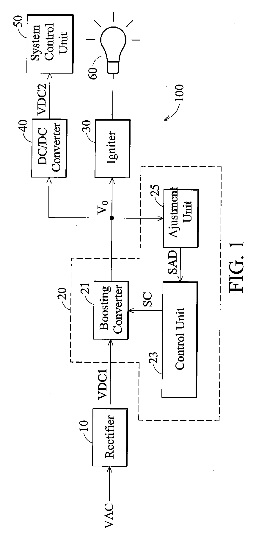
[0013]FIG. 1 shows an embodiment of a projector. As shown, a projector 100 comprises a rectifier 10, a power factor correction circuit 20, an igniter 30, a DC / DC converter 40 and a system control unit 50 and a lamp 60.

[0014]The rectifier 10 rectifies a system alternate-current (AC) power source, thereby outputting a rectified voltage V(t). For example, the rectifier 10 can be a full bridge rectifier, but is not limited thereto. In this embodiment, the rectified voltage V(t) output from the rectifier 10 comprises a voltage with ripple, and the amplitude of ripple depends on the capacitor C0 and / or time.

[0015]The power factor correction circuit 20 converts the rectified ...


PUM


Abstract

Power factor correction circuits are provided, in which a boosting converter comprises a switching element and an inductor, to convert a rectified voltage to a DC output voltage. An adjustment unit comprises a thermister with positive temperature coefficient, to generate an adjustment signal according to a present temperature and the DC output voltage. A control unit controls a duty cycle of the switching element according to the adjustment signal, thereby adjusting the voltage difference between the rectified voltage and the DC output voltage.

Description

BACKGROUND OF THE INVENTION[0001]1. Field of the Invention[0002]The invention relates to a power supply circuit, and in particular to a power supply circuit applied to projectors.[0003]2. Description of the Related Art[0004]Conventional display apparatus, such as cathode-ray tube (CRT) or liquid crystal displays (LCD), can only provide an image up to 30 40 inches wide and are inconvenient to transport. Projectors, capable of outputting an image up to tens or hundreds inches wide and is much smaller, easily outperforms both CRT display and LCD in terms of entertainment or business.[0005]Conventional projectors each comprise a power factor correction circuit to provide a fixed DC voltage regardless of temperature to a DC / DC converter and an igniter. Because the majority of power is provided by the power factor correction circuit, thermal design challenges can be reduced if the efficiency of the power factor correction circuit is improved and loss reduced.BRIEF SUMMARY OF THE INVENTION...

Claims


Application Information

Patent Timeline
IPC IPC(8): H02M7/217
CPCY02B70/126H02M1/4225Y02B70/10
Inventor CHEN, CHUAN-CHU
Owner BENQ CORP
Learn More