Output current compensation for jitter in input voltage for dimmable LED lamps

Active Publication Date: 2014-08-28
DIALOG SEMICONDUCTOR
View PDF6 Cites 19 Cited by
  • Summary
  • Abstract
  • Description
  • Claims
  • Application Information

AI Technical Summary

Benefits of technology

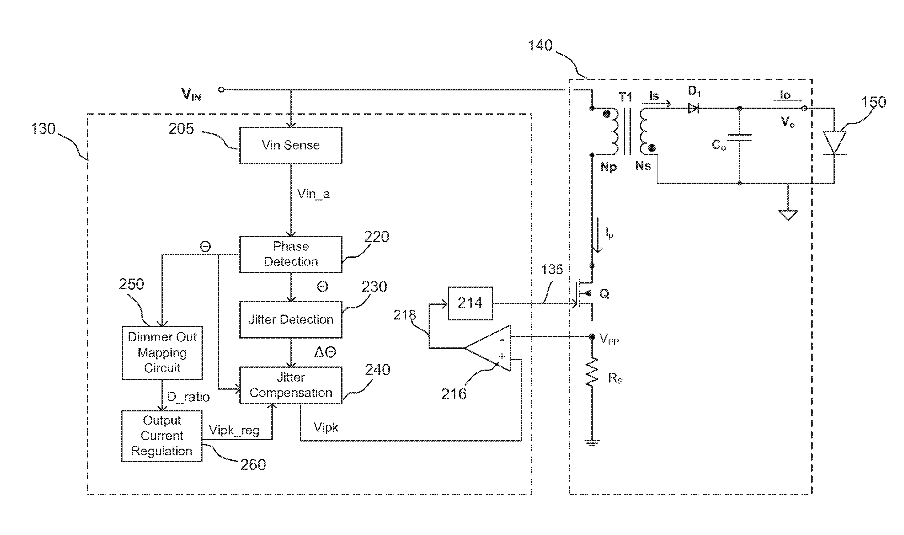
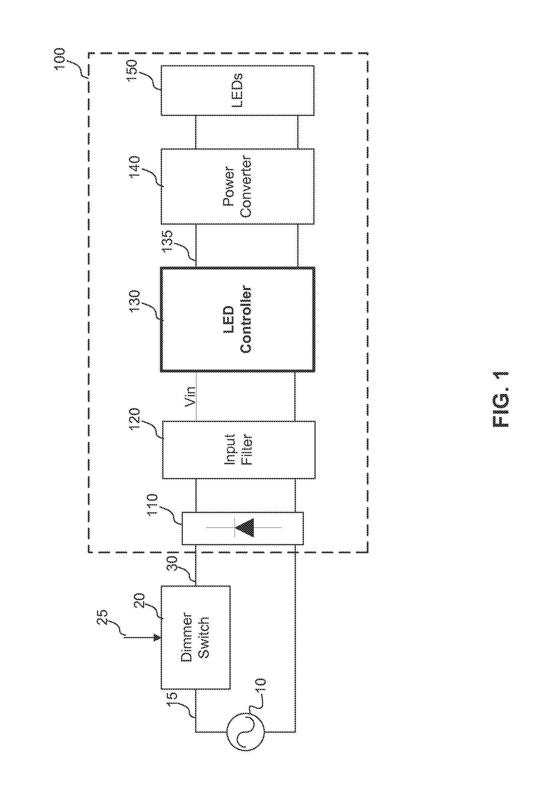
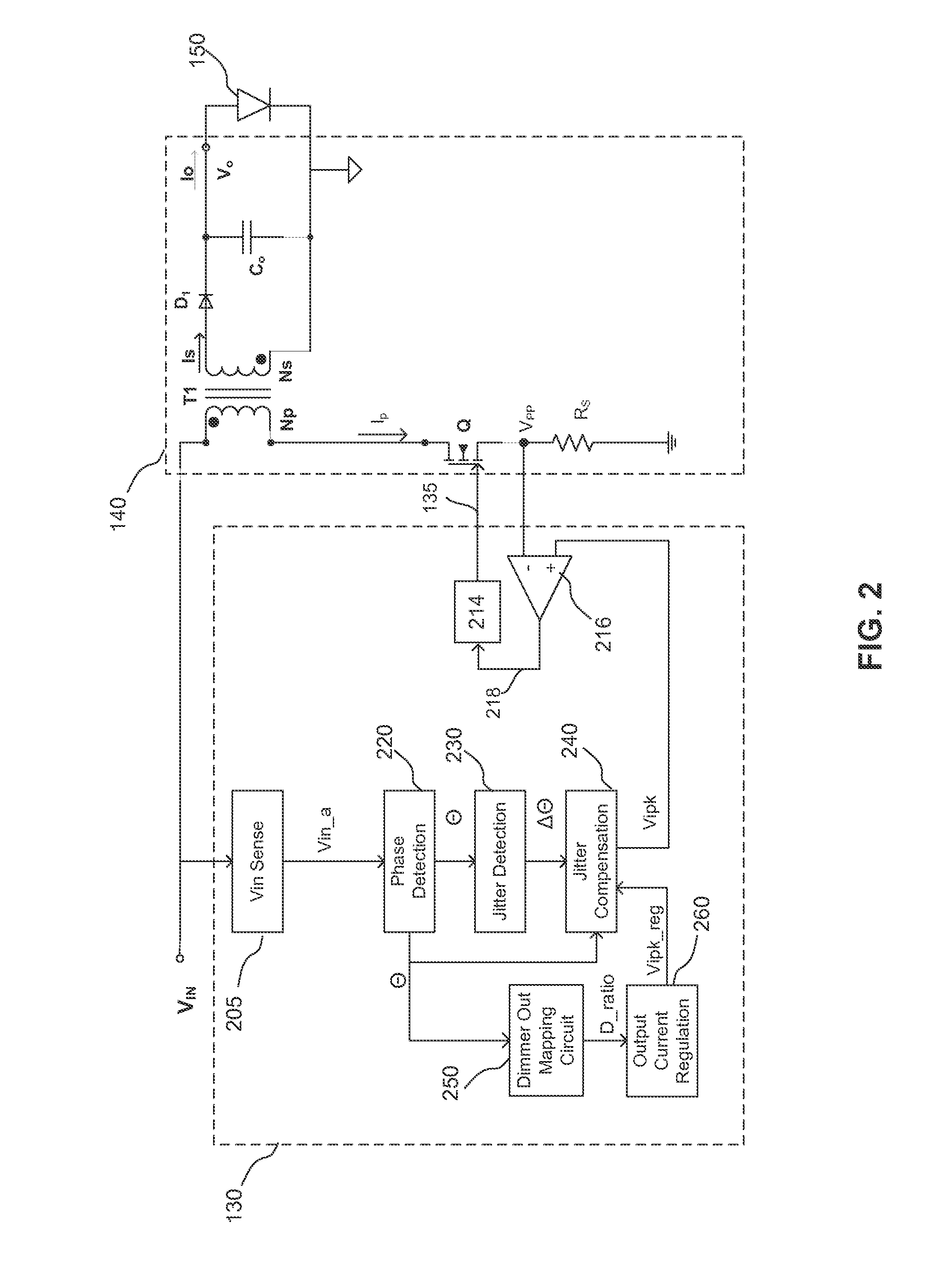
This invention offer an LED controller that can reduce the jitter of an LED lamp. It receives an input voltage signal that indicates the desired dimming amount of the LED lamp, and it detects the amount of jitter in the signal. The controller generates a control signal to adjust the current in the LED lamp so that its output light intensity matches the desired dimming level. To compensate for the jitter in the input signal, the controller disables current delivery to the LED lamp during certain parts of the input signal. This invention helps to achieve a smoother and more stable dimming effect for LED lamps.

Problems solved by technology

Furthermore, LED lamps represent lower environmental impact compared to fluorescent lighting systems (fluorescent ballast combined with fluorescent lamp) that may cause mercury contamination as a result of fluorescent lamp disposal.
However, conventional LED lamps cannot be direct replacements of incandescent lamps and dimmable fluorescent systems without modifications to current wiring and component infrastructure that have been built around incandescent light bulbs.
However, conventional dimmer switches that control the phase angle of the input voltage are not compatible with conventional LED lamps, since LEDs, and thus LED lamps, are current-driven devices.
However, due to asymmetrical electrical characteristics of dimmer switches, the adjusted phase angle may exhibit low-frequency jittering patterns.
The jitter can cause low-frequency LED light flickering that is detectable by the human eye.

Method used


Image

  • Output current compensation for jitter in input voltage for dimmable LED lamps
  • Output current compensation for jitter in input voltage for dimmable LED lamps
  • Output current compensation for jitter in input voltage for dimmable LED lamps

Examples


Embodiment Construction

[0019]The Figures (FIG.) and the following description relate to preferred embodiments by way of illustration only. It should be noted that from the following discussion, alternative embodiments of the structures and methods disclosed herein will be readily recognized as viable alternatives that may be employed without departing from the principles of the claimed invention.

[0020]Reference will now be made in detail to several embodiments of the present invention(s), examples of which are illustrated in the accompanying figures. It is noted that wherever practicable similar or like reference numbers may be used in the figures and may indicate similar or like functionality. The figures depict embodiments of the present invention for purposes of illustration only. One skilled in the art will readily recognize from the following description that alternative embodiments of the structures and methods illustrated herein may be employed without departing from the principles of the invention...


PUM


Abstract

An LED controller reduces jitter of an LED lamp. In one embodiment, the LED controller includes a jitter detection circuit adapted to determine an amount of jitter in an input voltage signal. The input voltage signal includes a plurality of cycles and indicates an amount of dimming for the LED lamp. The LED controller further includes a jitter compensation circuit, which generates a control signal to control regulated in the LED lamp such that an output light intensity of the LED lamp substantially corresponds to the amount of dimming for the LED lamp. The control signal controls current delivery to the LED lamp to compensate for the determined amount of jitter in the input voltage signal.

Description

CROSS-REFERENCE TO RELATED APPLICATIONS[0001]This application claims the benefit of U.S. Provisional Application No. 61 / 770,280, filed on Feb. 27, 2013, which is incorporated herein by reference in its entirety.BACKGROUND OF THE DISCLOSURE[0002]1. Field of the Invention[0003]This disclosure relates to driving LED (Light-Emitting Diode) lamps and, more specifically, to compensating for jitter in the LED lamps.[0004]2. Description of the Related Art[0005]LEDs are being adopted in a wide variety of electronics applications, for example, architectural lighting, automotive head and tail lights, backlights for liquid crystal display devices, flashlights, etc. Compared to conventional lighting sources such as incandescent lamps and fluorescent lamps, LEDs have significant advantages, including high efficiency, good directionality, color stability, high reliability, long life time, small size, and environmental safety.[0006]The use of LEDs in lighting applications is expected to expand, as ...

Claims


Application Information

Patent Timeline
IPC IPC(8): H05B33/08H05B44/00
CPCH05B33/0815H05B45/10Y02B20/30H05B45/3725H05B45/385H05B45/14
Inventor WANG, XIAOYANYAN, LIANGSHI, NAN
Owner DIALOG SEMICONDUCTOR
Why Eureka
Try Eureka