Constant-voltage and constant-current buck converter and control circuit

a converter and constant-current technology, applied in the direction of dc-dc conversion, power conversion systems, instruments, etc., can solve the problem that the output voltage is often affected by the input line, and achieve the effect of reducing the voltag

Active Publication Date: 2014-08-28
BCD SHANGHAI MICRO ELECTRONICS CO LTD
View PDF6 Cites 14 Cited by
  • Summary
  • Abstract
  • Description
  • Claims
  • Application Information

AI Technical Summary

Benefits of technology

[0034]In another embodiment, the control circuit also includes a power terminal (VCC) for receiving operating power, said power terminal is coupled to a center tap point of the inductor for reducing the voltage at the VCC terminal.

Problems solved by technology

However, in a non-isolated buck converter with constant voltage control, the output voltage is often affected by the input line voltage because the output stage usually shares a ground terminal or supply terminal with the input circuit.

Method used


Image

  • Constant-voltage and constant-current buck converter and control circuit
  • Constant-voltage and constant-current buck converter and control circuit
  • Constant-voltage and constant-current buck converter and control circuit

Examples


Embodiment Construction

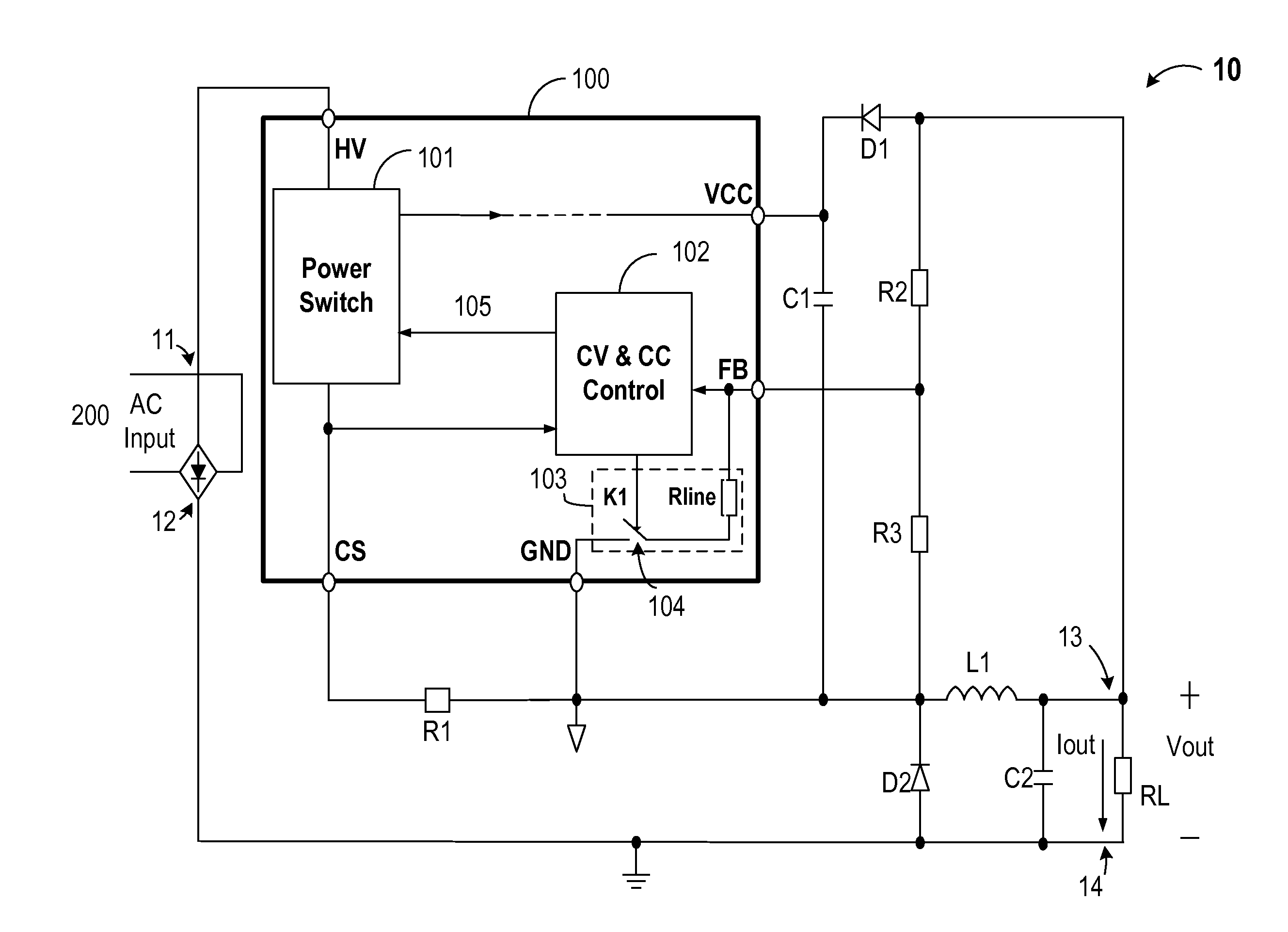
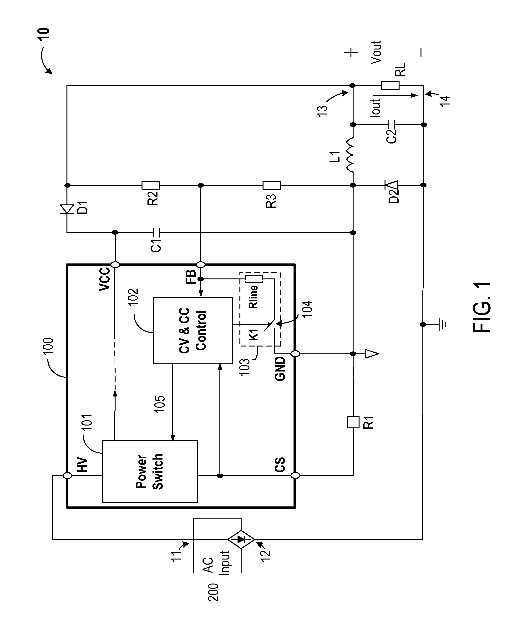
[0045]Embodiments of the present invention provide techniques related to operation of a switched mode power supply. More particularly, the present invention provides a method and system for constant voltage (CV) and constant-current (CC) control of a buck converter power supply. Merely by way of example, the present invention has been applied to a buck converter of a non-isolated type, but it would be recognized that the invention has a much broader range of applications.

[0046]The description below is presented with reference to a series of drawing figures enumerated above. These diagrams are merely examples, and should not unduly limit the scope of the claims herein. In connection with the various aspects illustrated and described, one of ordinary skill in the art would recognize other variations, modifications, and alternatives.

[0047]FIG. 1 is a simplified circuit / block diagram illustrating a switch-mode power supply including a buck converter according to an embodiment of the pre...


PUM


Abstract

A control circuit is provided for a buck converter that includes at least an inductor coupled to an output of the buck converter. The control circuit includes a power switch configured for coupling to a line voltage and configured for charging the inductor, an input line voltage sampling circuit, and a constant-voltage (CV) and constant-current (CC) control module coupled to the power switch. During a charging period of the inductor, the CV and CC control module is configured to control the power switch to provide a constant output current by maintaining a constant peak inductor current, even when the input line voltage changes. During a discharging period of the inductor, the CV and CC control module is configured to monitor the sensed output voltage to control the power switch to provide a constant output voltage.

Description

CROSS-REFERENCES TO RELATED APPLICATIONS[0001]This application claims priority to Chinese Patent Application No. 201310064413.1, filed on Feb. 28, 2013, which is commonly owned and incorporated by reference herein.BACKGROUND OF THE INVENTION[0002]Embodiments of the present invention are directed to power supply control circuits and power supply systems. More particularly, embodiments of the invention provide methods and circuits for constant-voltage and constant-current control of non-isolated buck converter switched mode power supply (SMPS). But it would be recognized that the invention has a much broader range of applicability.[0003]Regulated power supplies are indispensable in modern electronics. For example, the power supply in a personal computer often needs to receive power input from various outlets. Desktop and laptop computers often have regulated power supplies on the motherboard to supply power to the CPU, memories, and periphery circuitry. Regulated power supplies are al...

Claims


Application Information

Patent Timeline
Patent Type & Authority Applications(United States)
IPC IPC(8): H02M3/10H02M1/00
CPCH02M3/10H02M3/156H02M7/2176H02M1/0022H02M1/08H02M1/0009
Inventor WANG, HUZHU, YAJIANGFEI, RUIXIALV, SHUZHUANG
Owner BCD SHANGHAI MICRO ELECTRONICS CO LTD
Why Eureka
Try Eureka