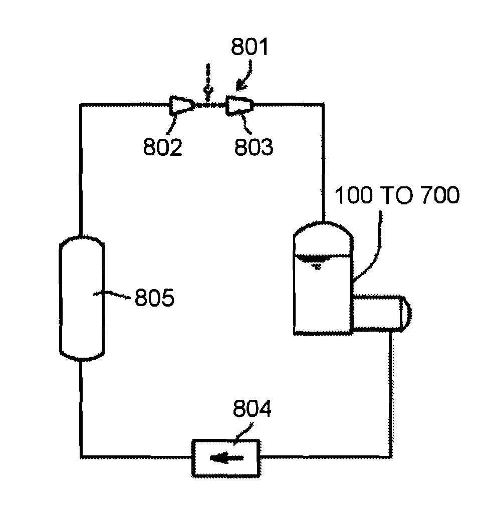
Quench tank and liquid metal loop
- Summary
- Abstract
- Description
- Claims
- Application Information
AI Technical Summary
Benefits of technology
Problems solved by technology
Method used
Image
Examples
first embodiment
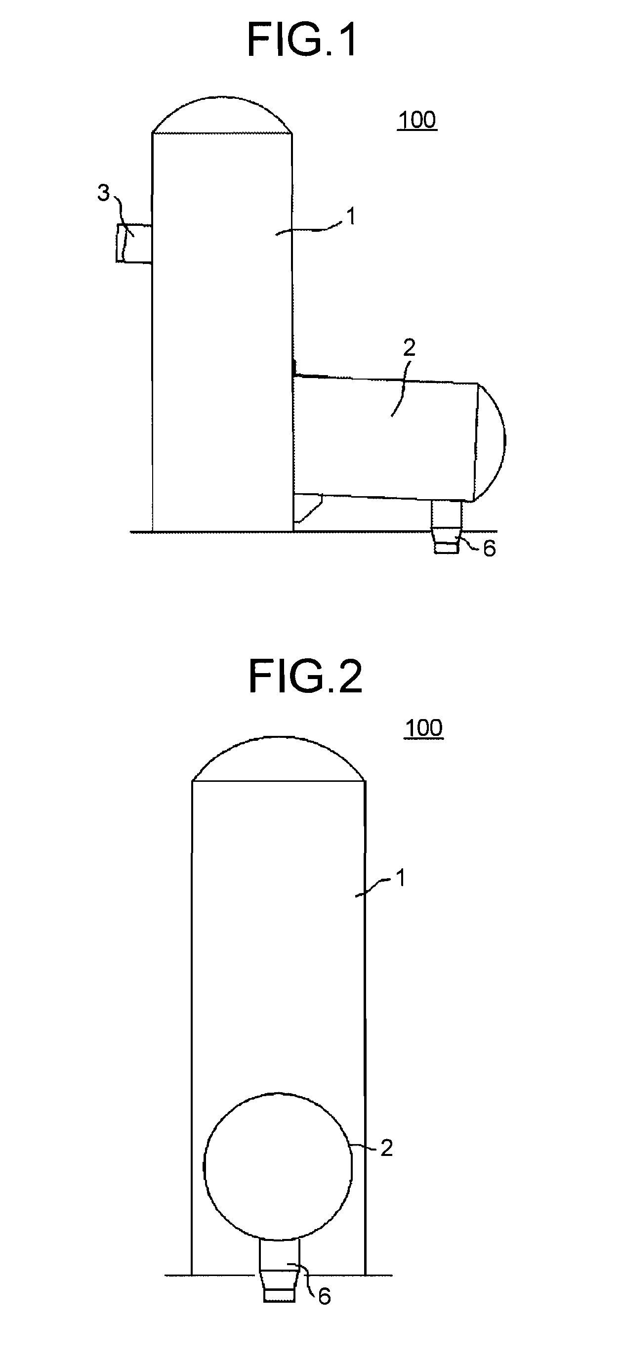
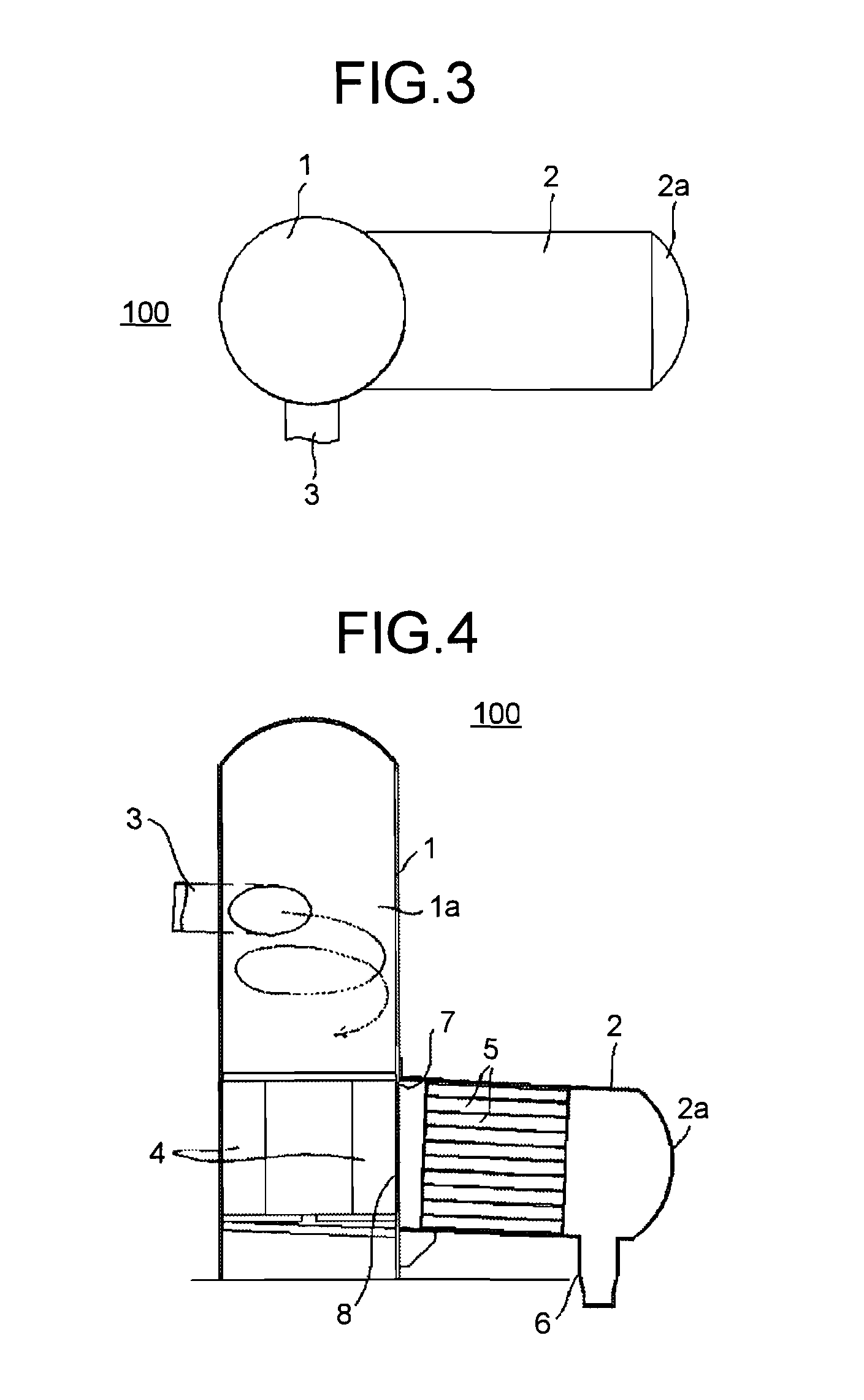
[0033]FIG. 1 is a front view illustrating a quench tank according to a first embodiment of the invention. FIG. 2 is a side view of the quench tank illustrated in FIG. 1, and FIG. 3 is a top view. FIG. 4 is a cross-sectional view of the quench tank illustrated in FIG. 1. A quench tank 100 includes a tank body 1 which is connected to a receiving portion of a target forming portion for forming a liquid metal target by a tube and a cylindrical body 2 which is formed in the lower portion of the tank body 1 in the substantially horizontal direction.
[0034]The tank body 1 is a structure which is formed in a cylindrical shape by sheet-metal processing. A tube 3 which extends from the target forming portion is provided at the upper side surface of the tank body 1 in a direction tangent to the cylinder of the tank body 1. Accordingly, the liquid metal which is introduced from the tube 3 enters a free liquid level while rotating along an inner surface 1a of the tank body 1 (the flow of the liqu...
second embodiment
[0045]FIG. 6 is a cross-sectional view illustrating a cylindrical body of a quench tank according to a second embodiment of the invention. The quench tank has substantially the same configuration as that of the first embodiment, but the shape and the arrangement of the separating plate 5 are different. Since the other configurations are the same as those of the quench tank 100 of the first embodiment, the description thereof will not be repeated. In the quench tank, a punching metal plate with a plurality of holes 202 is provided as a separating plate 201, and a plurality of the punching metal plates are substantially arranged in the horizontal direction. The liquid metal which flows out of the tank body 1 passes between the layers of the plurality of separating plates 201. The bubbles contained in the liquid metal come into contact with the rear surfaces of the respective separating plates 201, and here, the bubbles are combined with each other so as to grow. The buoyant force of t...
third embodiment
[0049]FIG. 7 is a cross-sectional view illustrating a cylindrical body of a quench tank according to a third embodiment of the invention. FIG. 8 is a diagram illustrating an arrangement state of the separating plate. The quench tank according to the third embodiment has substantially the same configuration as that of the first embodiment, but the shape and the arrangement of a separating plate 301 are different. Since the other configurations are the same as those of the quench tank 100 of the first embodiment, the description thereof will not be repeated. In the quench tank 100, a separating plate 301 is curved about the axis in the length direction, where the cross-section is formed in an inverse concave dish shape and a plurality of holes 302 are provided in the vicinity of the apex in the length direction. Further, another separating plate 303 is curved about the axis in the length direction, where the cross-section is formed in an inverse concave dish shape and a hole 304 is pr...
PUM
| Property | Measurement | Unit |
|---|---|---|
| Angle | aaaaa | aaaaa |
| Length | aaaaa | aaaaa |
| Area | aaaaa | aaaaa |
Abstract
Description
Claims
Application Information
 - R&D
- Intellectual Property
- Life Sciences
- Materials
- Tech Scout
- Unparalleled Data Quality
- Higher Quality Content
- 60% Fewer Hallucinations
Browse by: Latest US Patents, China's latest patents, Technical Efficacy Thesaurus, Application Domain, Technology Topic, Popular Technical Reports.
© 2025 PatSnap. All rights reserved.Legal|Privacy policy|Modern Slavery Act Transparency Statement|Sitemap|About US| Contact US: help@patsnap.com


