Hybrid ferrule and fiber optical test device

Active Publication Date: 2014-08-28
LIFODAS UAB
View PDF19 Cites 6 Cited by
  • Summary
  • Abstract
  • Description
  • Claims
  • Application Information

AI Technical Summary

Benefits of technology

The present invention relates to a hybrid ferrule for use in an MPO connector. The hybrid ferrule has a triangular-shaped gap between the fiber end of the hybrid ferrule and the fiber end of an MPO connector. This gap is smaller for a flat polished connector and larger for an angle polished connector, which ensures the widest point of the light acceptance cone created by light released from an angle polished connector is wider than the widest point of the light acceptance cone created by light released from a flat polished connector. The hybrid ferrule is designed to minimize insertion loss and prevent reflections caused by reflections between the hybrid ferrule and the fiber end. The angle of the third surface of the hybrid ferrule is designed to avoid measurement of unwanted light reflections. Overall, the present invention provides a hybrid ferrule that allows the MPO connector to be connected to either flat or angle polished ferrules.

Problems solved by technology

Currently, the main ‘problem is that, for different types of output connectors, people use the appropriate different types of input connectors because the geometry of output connectors are different.
Because typical MPO connectors are trying to align so many fibers at once, their coupling loss are typically larger than single fiber connectors.
However, the main problem in practice is, that for each type of signal (for example: MM, SM), a different type of ferrule (94) has to be used.
Connecting a flat polished ferrule to an angle polished ferrule results in high losses of the optical signal intensity and risk of mechanical damage of the surfaces of the ferrules.
Reflections of light can cause damage in the transmission system and in testing optical systems.
In some cases, physical contact between the ferrules is undesirable as it may abrade the ferrule ends, which may cause distorted measurements.
Such reflections cause signal interference and result in distorted measurements.
However it results in potential abrasion problems.

Method used


Image

  • Hybrid ferrule and fiber optical test device
  • Hybrid ferrule and fiber optical test device
  • Hybrid ferrule and fiber optical test device

Examples


Embodiment Construction

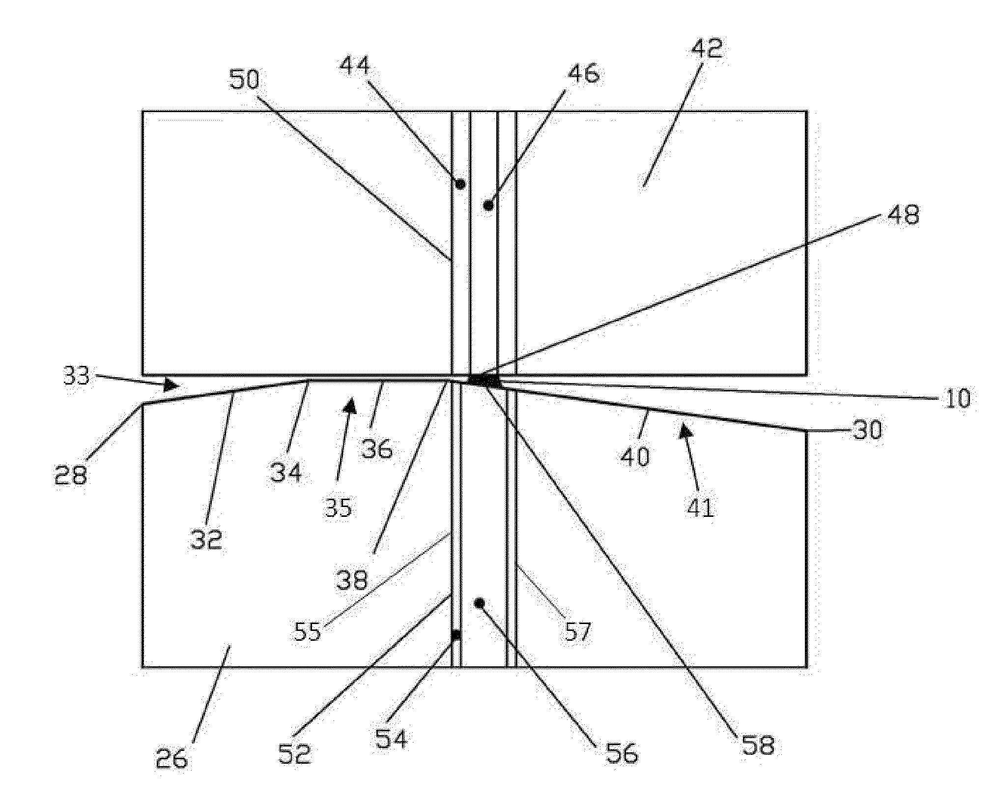
[0037]Referring first to FIG. 5, a top down view of hybrid ferrule (26) of the present invention is shown. Hybrid ferrule (26) has integrated end (27), connection end (29), right side (31), left side (25), flat center (23), left edge (28), right edge (30), and first point (34) and second point (38) are between left edge (28) and right edge (30). Connection end (29) is connected to another ferrule during testing. Integrated end (27) is the opposite end of connection end (29) and is incorporated into a test device. Flat center (23) is defined by connection end (29), integrated end (27), right side (31), and left side (25). First surface (32) angles up from left edge (28) on left side (25) to first point (34). Angle A, between first surface (32) and the dashed line on the left is approximately eight degrees (8°). First surface (32) and angle A are means for mating with an angle polished connector (33) indicated in FIG. 7A. Second surface (36) is flat between first and second points (34...


PUM


Abstract

The present invention is a hybrid ferrule which is able to be connected to both, angle polished and flat polished, MPO connectors; a test device including the above mentioned hybrid ferrule; and a test kit, including the above mentioned test device with hybrid ferrule. The hybrid ferrule of the present invention includes first, second, and third surfaces which are designed in a special way to ensure the high quality connection with SM or MM type connectors. A hybrid fiber connector having an integrated end, a connection end, two sides, a flat center, and an optical fiber embedded in the flat center parallel to and halfway between the two sides. The connection end includes left and right edges and first, second, and third surfaces. The first surface angles upward from said left edge of said connection end to a first point, the second surface extends flat between the first point and a second point, and a third surface angles downward between the second point and the right edge of said connection end.

Description

CLAIM OF PRIORITY[0001]This patent application is a non-provisional patent application claiming the benefit of priority of U.S. Provisional Patent Application Ser. No. 61 / 770,839, filed on Feb. 28, 2013.FIELD OF THE INVENTION[0002]The present invention relates to polished multiple-fiber push-on / pull-off (MPO / MTP) type fiber optical connectors and, in particular, to hybrid ferrules used in test devices, which can be connected with angled and / or flat fiber optic connectors.BACKGROUND[0003]To transfer the optical signal from one fiber cable to another one, the output and input cables' ends must be attached to output and input connectors of appropriate types; for example: males and / or females. Depending on the output signal type Single Mode (SM) or Multi Mode (MM), the appropriate input connector must be used. Currently, the main ‘problem is that, for different types of output connectors, people use the appropriate different types of input connectors because the geometry of output conne...

Claims


Application Information

Patent Timeline
IPC IPC(8): G02B6/38
CPCG02B6/3826G02B6/3885G02B6/3818G02B6/3863
Inventor LEVIN, PIOTR ANATOLIJ
Owner LIFODAS UAB
Why Eureka
Try Eureka