Optical Transceiver Device

a transceiver and optical technology, applied in the field of optical transceivers, can solve the problems of inability to reduce volume, inability to develop the trend of minimizing optical transceivers, and large volume of conventional optical transceivers, and achieve the effect of reducing the volume of the o/e transceiver module and further reducing the volume of the optical transceiver devi

Active Publication Date: 2014-08-28
AGILEIOTS INVESTMENT CO LTD
View PDF3 Cites 231 Cited by
  • Summary
  • Abstract
  • Description
  • Claims
  • Application Information

AI Technical Summary

Benefits of technology

[0019]In comparison to prior arts, for the optical transceiver device provided by the invention, the volume of the O/E transceiver module is reduced by integrating the plurality of O/E transceiver units into one integrated chip to form an integrated O/E transceiver module.
[0020]Furthermore, the optical switching module provided by the invention may switch optical channels with a mirror total reflection principle

Problems solved by technology

Because of limited number of optical signal transmitting channels provided by a single O/E transceiver, as optical transceiver devices are connected to multiple optical network equipments, multiple O/E transceivers have to be provided therein, such that O/E transceiving modules are maximized, which

Method used


Image

  • Optical Transceiver Device
  • Optical Transceiver Device
  • Optical Transceiver Device

Examples


Embodiment Construction

[0035]Embodiments of the present invention will now be described in detail with reference to the accompanying drawings. The invention may, however, be embodied in many different forms and should not be construed as being limited to the embodiments set forth herein. Rather, these embodiments are provided so that this disclosure will be thorough and complete, and will fully convey the scope of the invention to those skilled in the art. In the drawings, the shapes and dimensions of elements may be exaggerated for clarity, and the same reference numerals will be used throughout to designate the same or like components.

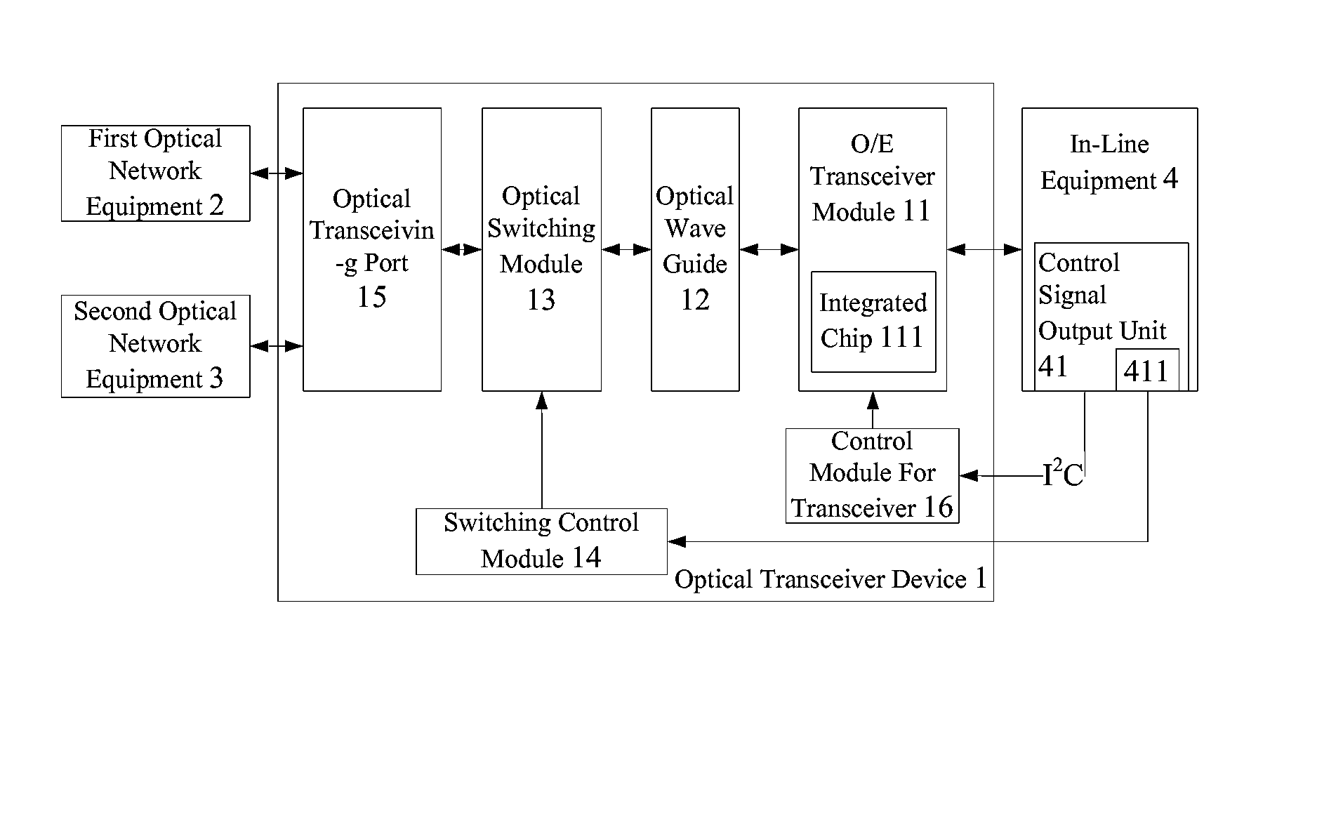
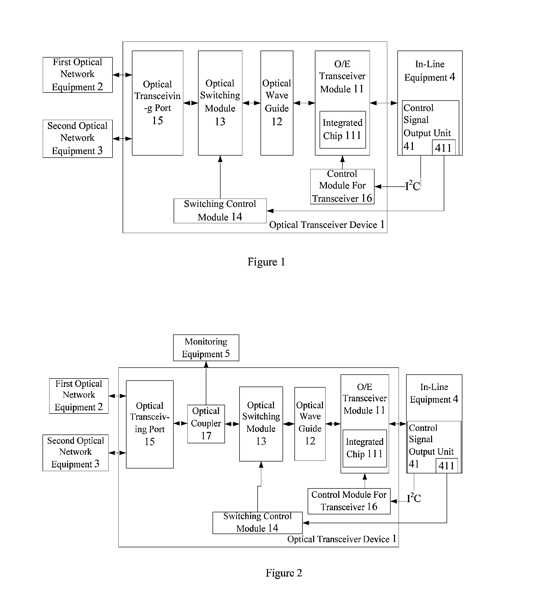
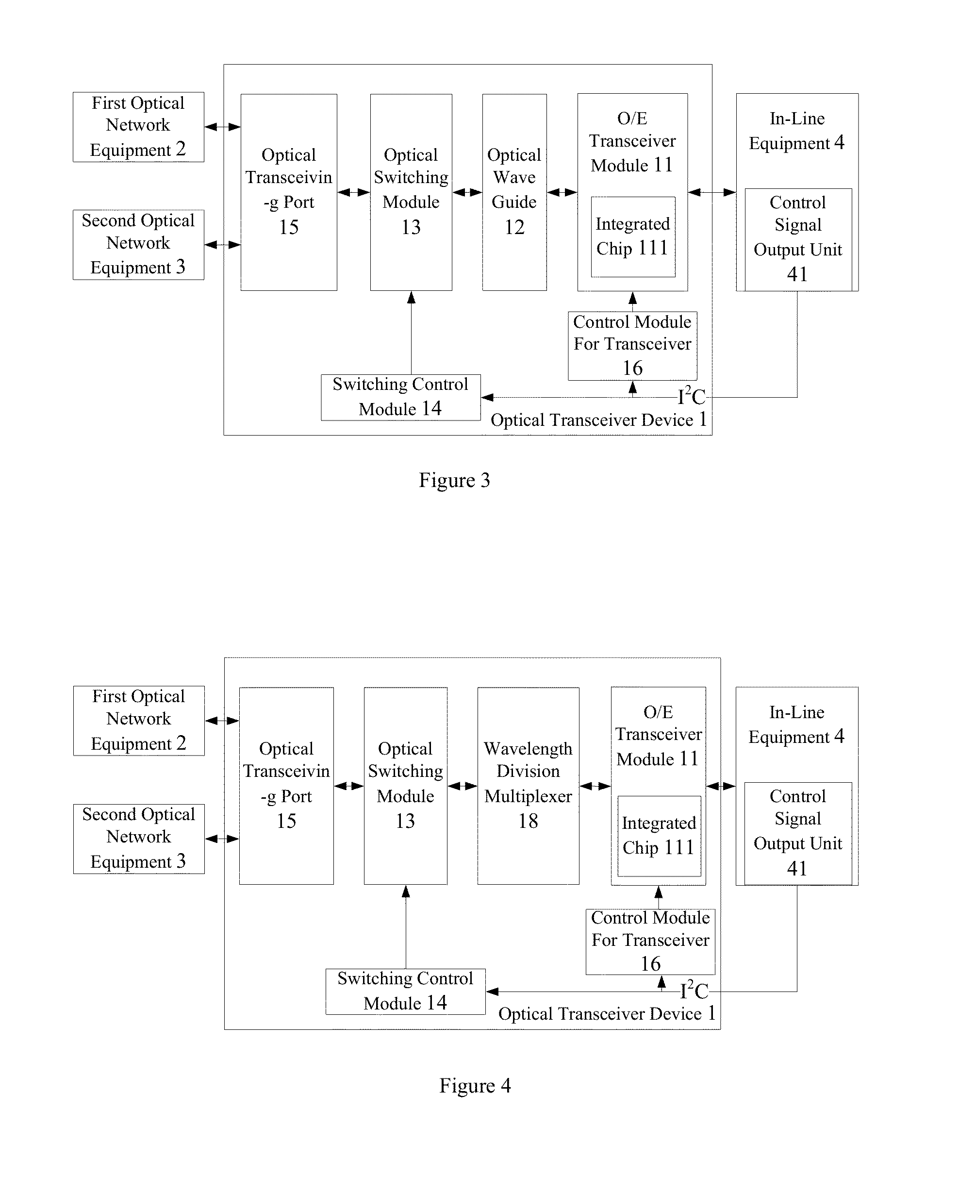
[0036]Refer to FIGS. 1 to 4, which are system structure diagram showing various examples of optical transceiver devices according to the invention, wherein, identical or like elements are indicated by identical or like numerals in various examples without detailed description in order for more clear understanding of the technical description of the application. As shown in...


PUM


Abstract

An optical transceiver device is provided, including an O/E transceiver module, an optical switching module and a switching control module, for providing network communication services for a first and a second optical fiber network equipment. The O/E transceiver module is an integrated chip having multiple transceiver units integrated therein. The switching control module is connected to an in-line equipment and the optical switching module for controlling the optical switching module to execute corresponding optical path switching operation according to an optical path switching control signal output from the inline equipment. In comparison with conventional optical transceiver devices, the invention is advantageous of simple structure, smaller volume and more flexible optical path switching.

Description

CROSS-REFERENCE TO RELATED APPLICATIONS[0001]This application claims the priority of Republic of China Patent Application No. 102106614 filed on Feb. 25, 2013 and No. 102133827 filed on Sep. 18, 2013, in the State Intellectual Property Office of the P.R.C., the disclosure of which is incorporated herein by reference.BACKGROUND OF THE INVENTION[0002]1. Field of the Invention[0003]The invention relates to an optical transceiver device, particularly to an optical transceiver device with smaller volume and simpler structure.[0004]2. Descriptions of the Related Art[0005]With the rapid development of network technologies, optical communication technology has become a major communication technology developed currently because of several advantages, including rapid transmission speed, long transmission distance, capability of anti-electromagnetic interference, and high security etc.[0006]Conventional optical transceiver devices are mainly formed by O / E transceivers, optical switching switch...

Claims


Application Information

Patent Timeline
IPC IPC(8): H04B10/40H04Q11/00
CPCH04B10/40H04Q11/0001
Inventor JIANG, SEAN
Owner AGILEIOTS INVESTMENT CO LTD
Why Eureka
Try Eureka