
System and method for free space optical communication beam acquisition

a free space optical communication and beam acquisition technology, applied in the field of optical communication, can solve the problems of system failure to distinguish between transmitted and reflected signals, signal strength falling below the noise floor, and limited isolation within the optical circulator or bulk optical beam splitter

Inactive Publication Date: 2014-08-28
HARRIS CORP
View PDF28 Cites 37 Cited by
  • Summary
  • Abstract
  • Description
  • Claims
  • Application Information

AI Technical Summary

Benefits of technology

This patent describes a system for transmitting and receiving optical signals through an optical fiber using two mono-static transceivers. Each transceiver has a reflective surface that reflects signals in a specific field of view. The system includes an acquisition system that detects a modulated signal and adjusts the alignment of the transceivers accordingly to ensure proper signal transmission. The technical effects of this invention include improved signal transmission and alignment accuracy between optical fibers, leading to more efficient and reliable optical communication.

Problems solved by technology

As the distance increases, there is risk that the two-way path loss will cause the signal strength to fall below the noise floor caused by other optical sources, reflections or glints.
Furthermore, in a mono-static system, there is limited isolation within the optical circulator or bulk optical beam splitter.
If the signal strength of the retro-reflective signal is less than the isolation, the system will not be able to differentiate between the transmitted and reflected signals

Method used


Image

  • System and method for free space optical communication beam acquisition
  • System and method for free space optical communication beam acquisition
  • System and method for free space optical communication beam acquisition

Examples


Embodiment Construction

[0028]In the drawings, like numerals indicate like elements throughout. Certain terminology is used herein for convenience only and is not to be taken as a limitation on the present invention. The following describes preferred embodiments of the present invention. However, it should be understood, based on this disclosure, that the invention is not limited by the preferred embodiments described herein.

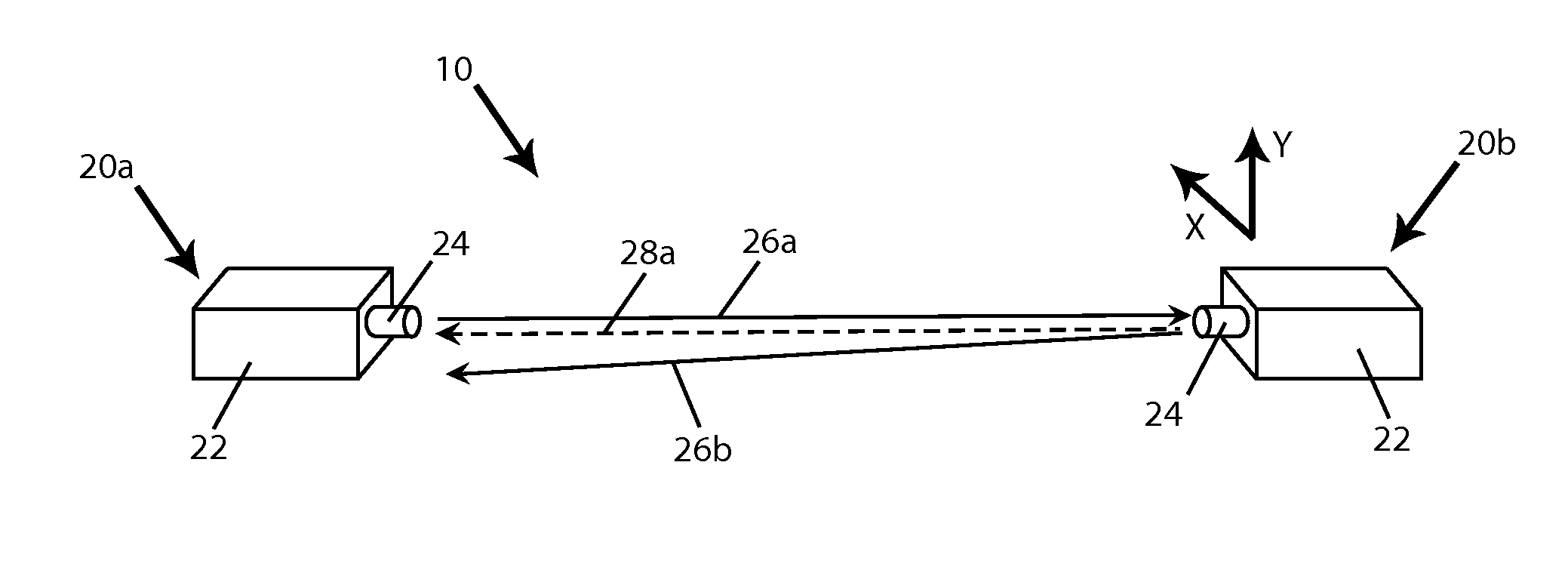
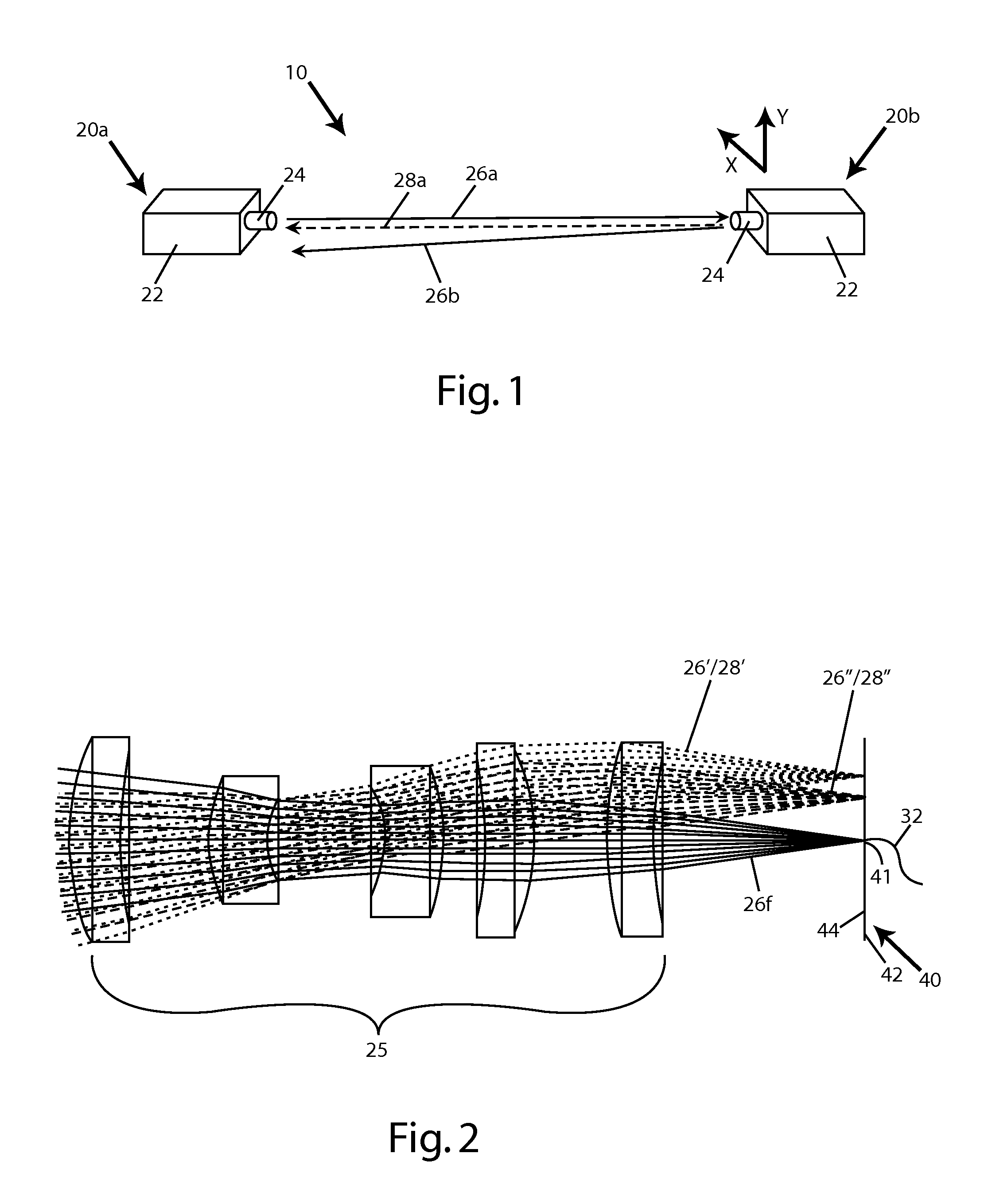
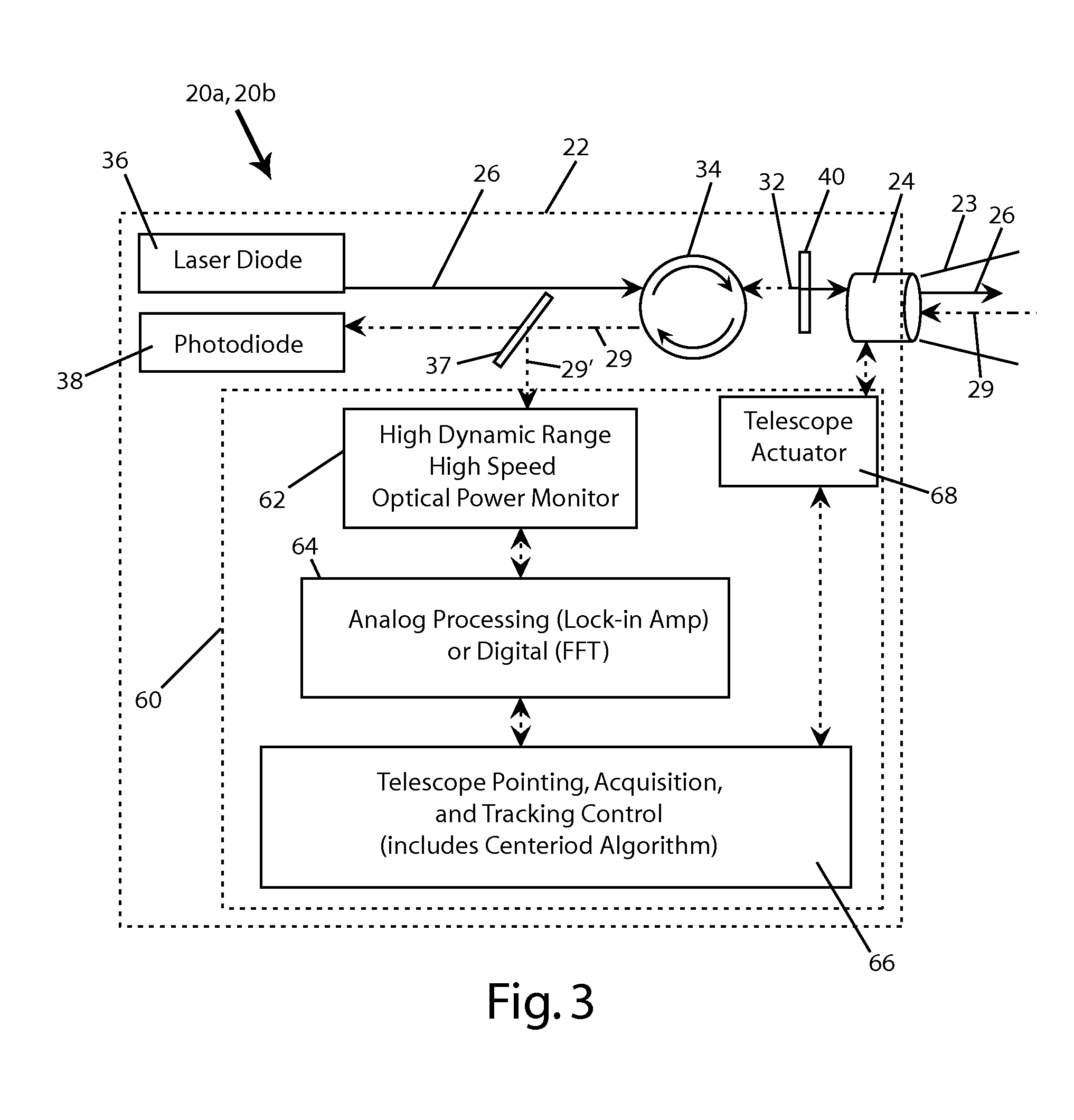
[0029]Referring to FIGS. 1-3, the exemplary free space optical communication system 10 includes a pair of mono-static transceivers 20a and 20b. Each transceiver 20a and 20b includes a single telescope 24 extending from a housing 22. The system 10 may be configured such that one or both housings 22 are adjustable in the X and Y planes, or one or both housings 22 may be fixed and the internal components adjustable in the X and Y planes to align the telescopes 24.

[0030]As illustrated in FIGS. 2 and 3, each telescope 24 includes one or more lenses or other optical components 25 which defin...


PUM


Abstract

A free space optical communication system (10) including first and second mono-static transceivers (20a, 20b). Each transceiver (20a, 20b) includes a reflective assembly (40) defining a reflective surface (44) about a receiving end of a respective optical fiber (32) and configured to reflect optical signals (26) within a field of view of the transceiver (20a, 20b) as a modulated retro-reflective signal (28). Each mono-static transceiver (20a, 20b) includes an acquisition system (60) configured to detect a modulated retro-reflective signal (28) and adjust the alignment of the respective transceiver (20a, 20b) in response to a detected modulated retro-reflective signal (28). A mono-static transceiver and a method of aligning a mono-static transceiver are also provided.

Description

FIELD OF THE INVENTION[0001]The present invention relates to the field of optical communications, and in particular to the field of beam steering for mono-static bidirectional free space optical transceivers. More particularly, the present invention relates to a beam pointing and tracking system and method utilizing pulsed beams to assist in target acquisition.BACKGROUND OF THE INVENTION[0002]Optical communications systems are today employed in a vast array of applications, including without limitation communication with aircraft and satellites from ground positions. A unidirectional optical communications system generally consists of a transmitting terminal and a receiving terminal while a bidirectional system includes a pair of transceivers, each of which acts as both a transmitting terminal and a receiving terminal. In either system, a transmitting terminal typically receives an electrical signal from a signal source, converts the electrical signal into an optical signal and then...

Claims


Application Information

Patent Timeline
Patent Type & Authority Applications(United States)
IPC IPC(8): H04B10/11
CPCH04B10/11H04B10/1127H04B10/118
Inventor PEACH, ROBERT C.BURDGE, GEOFFREY L.TIDWELL, TERRYVICKERS, JOHN GRADY
Owner HARRIS CORP
Learn More