Reactor and method for production of silicon by chemical vapor deposition

a technology of chemical vapor deposition and reactor, which is applied in the field of silicon manufacturing, can solve the problems of not being able to continue the process of silicon manufacturing, and achieve the effect of simple post-processing of silicon blocks and commercial access to sand/particles

Active Publication Date: 2014-08-28
DYNATEC ENG
View PDF10 Cites 3 Cited by
  • Summary
  • Abstract
  • Description
  • Claims
  • Application Information

AI Technical Summary

Benefits of technology

[0025]The particle layer can comprise small and / or large particles that are hollow, compact or porous or with varying porosity in the form of a dust, powder, sand, small balls or other small particles that are placed or settle as a thin layer on the inside of the reactor or the inner wall of the container. It is an advantage to place or spray a thin layer of powder, small balls or other small particles on the inside of the reactor wall. The centripetal forces that arise in the rotating reactor container will hold the particles in place on the wall at the same time as they will help to form a layer with a circular inner cross section. The particles are distributed evenly over the inner wall of the reactor cylinder by the centripetal force after the reactor has been made to rotate.
[0026]The particles ought to be of a material that leads to very little contamination and does not fuse together or stick to each other at the operating temperature of the reactor. Particles of pure silicon are most preferred, but silicon nitrite and quartz are good alternatives. Commercial access to sand / particles of these materials is good and this will therefore be a cheaper alternative than reactors manufactured with a wall of a pipe section in the same material. By the use of super pure, fine silicon sand, at least innermost against the reactor body, the post-processing of the silicon block will be very simple as there is no need to remove a layer of a different material outermost on the block of silicon. Particles of different sizes and shapes can be used. The layer can comprise several tiers of different types of particles. It is preferred that the particles innermost against the reactor wall will have a size and shape that leads to a good slip when the block of silicon shall be taken out of the reactor, while the particles nearest the reactor body shall be suitable as a deposit surface for deposition of silicon.

Problems solved by technology

With the Dynatec reactor, if the reactor shall be re-used, it can be a challenge to remove the completed block of silicon from the reactor after so much silicon has been deposited inside the reactor that it is not appropriate to continue the process for the manufacture of silicon.

Method used


Image

  • Reactor and method for production of silicon by chemical vapor deposition
  • Reactor and method for production of silicon by chemical vapor deposition
  • Reactor and method for production of silicon by chemical vapor deposition

Examples


Embodiment Construction

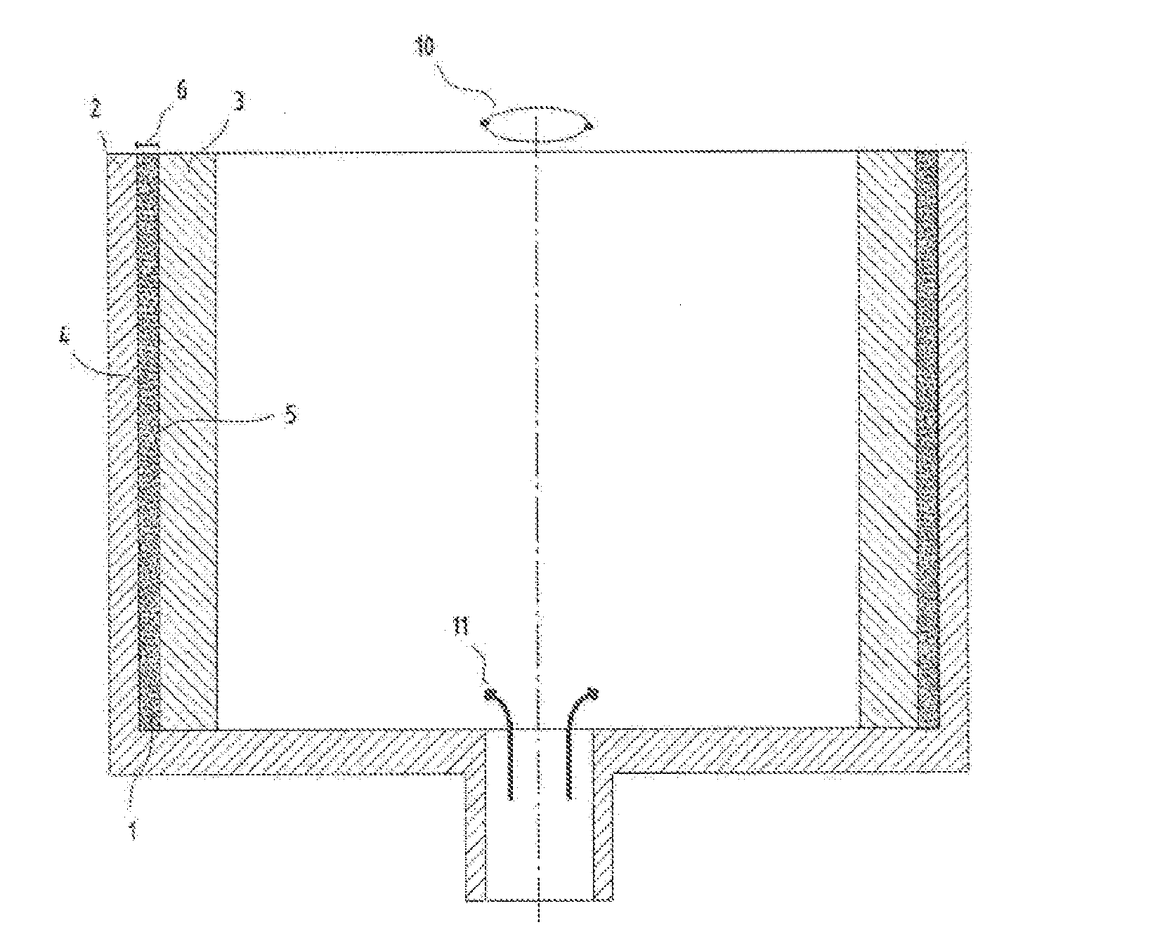
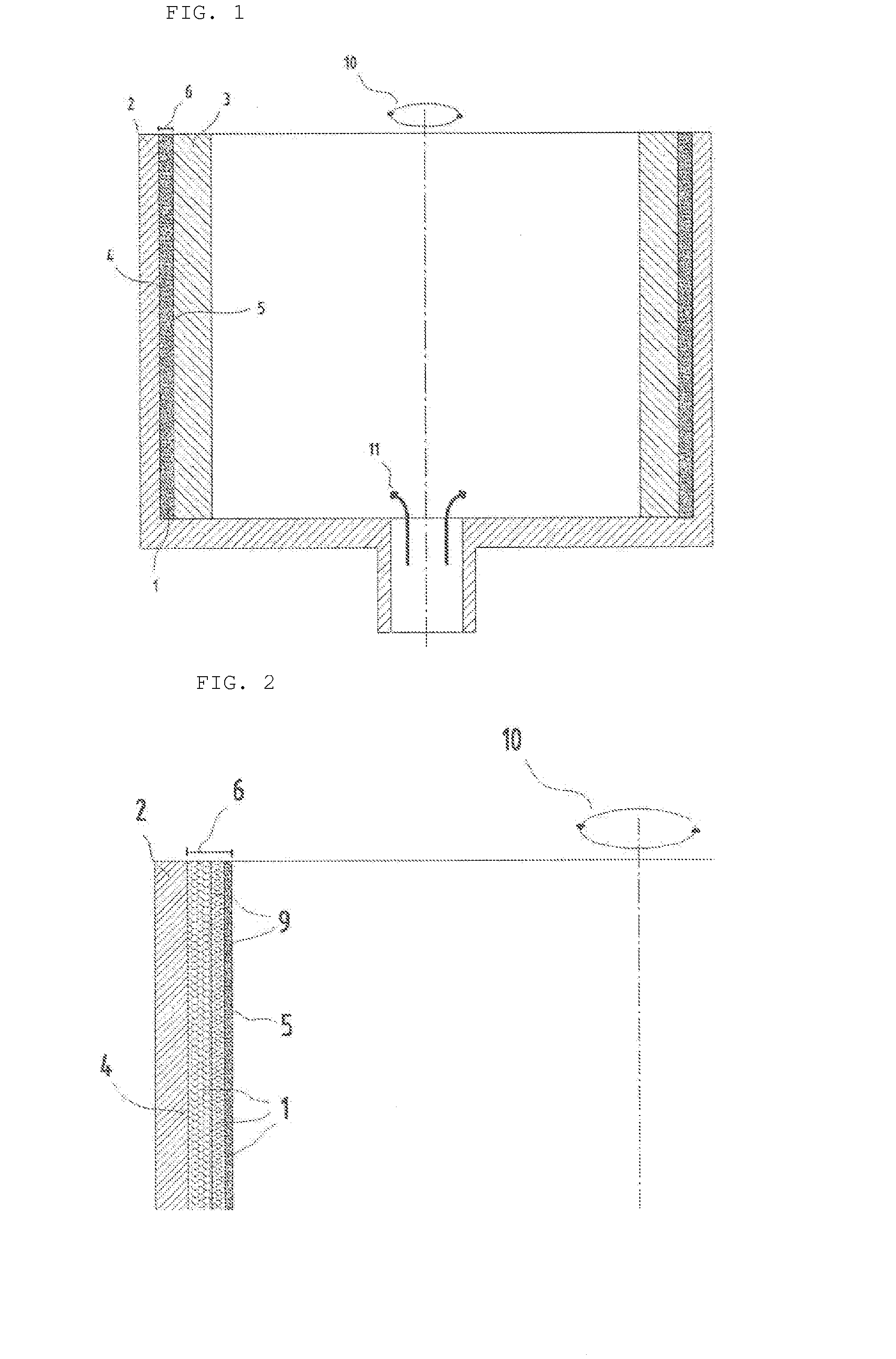
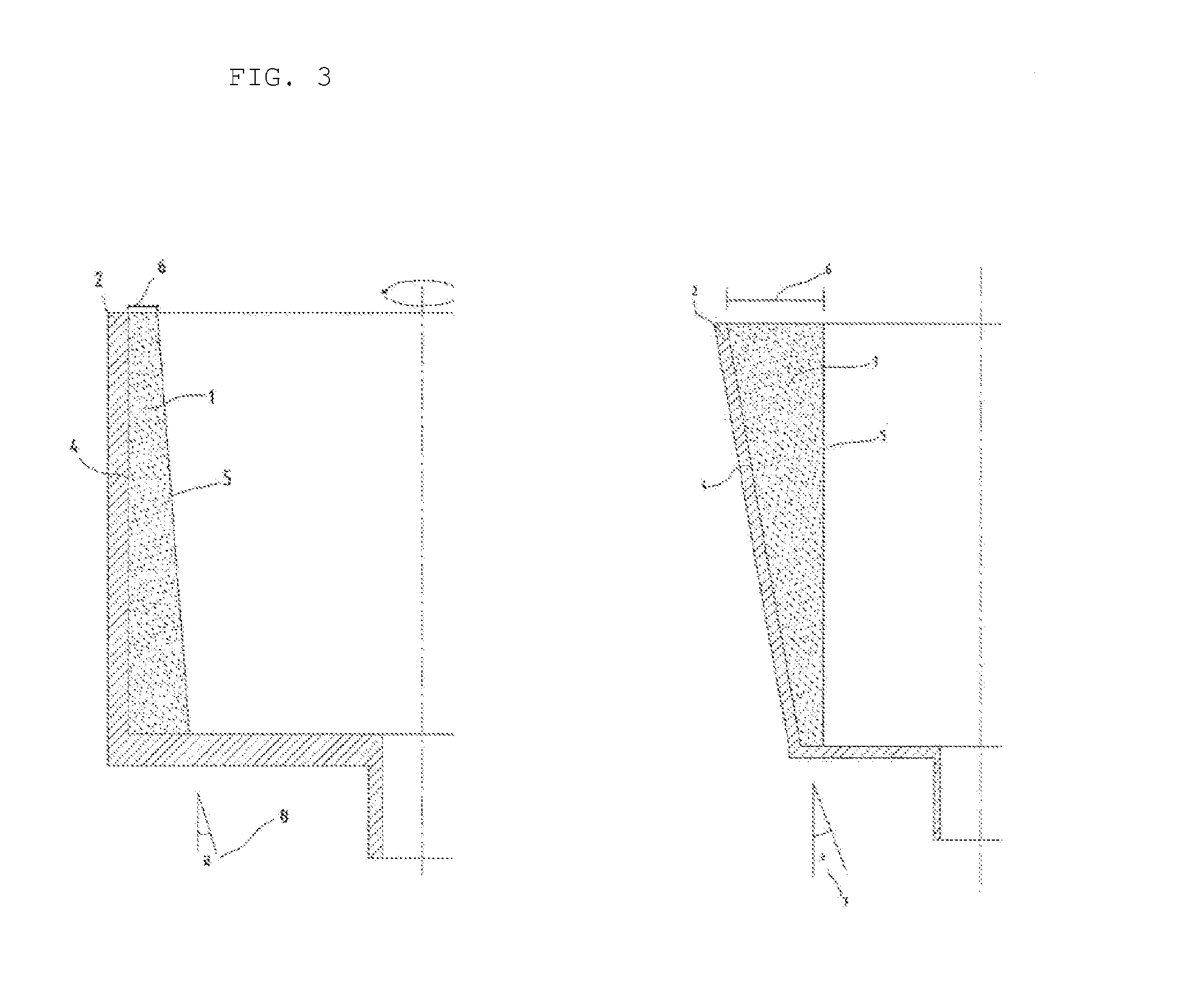
[0033]Reference is made to FIG. 1. The reactor comprises, in the main, a container (2), preferably formed as a cylinder with a circular, or approximately circular cross section, with an inlet for gas at the one end and an outlet at the other end or same end, and with the supply of heat on the outside and possibly on the inside too. The reactor is operatively arranged to an appliance to set the reactor in rotation (10), such as a motor. The particles (1) are distributed over the inner wall (4) of the reactor container (2) after it has been made to rotate (10) so that there will be an even layer of particles on the whole of the reactor wall (4). Thereby, the particles (1) will lie as a layer of particles (6) on the inside (4) of the reactor tube (2) and appear as an inner tube in the reactor container (2). The silicon deposits (3) will first be formed on the inside (5) of the particle layer (6).

[0034]The particles (1) can be in the form of sand, dust or small balls in a hollow, porous...


PUM

PropertyMeasurementUnit
purityaaaaaaaaaa
thicknessaaaaaaaaaa
diameteraaaaaaaaaa

Abstract

The invention provides a reactor for the manufacture of silicon by chemical vapour deposition (CVD), the reactor comprises a reactor body that can rotate around an axis with the help of a rotation device operatively arranged to the reactor, at least one sidewall that surrounds the reactor body, at least one inlet for reaction gas, at least one outlet for residual gas and at least one heat appliance operatively arranged to the reactor. The reactor is characterised in that during operation for the manufacture of silicon by CVD, the reactor comprises a layer of particles on the inside of at least, one sidewall.

Description

FIELD OF THE INVENTION[0001]The present invention relates to the manufacture of silicon for application in sun cells and electronics. In more detail, the invention relates to a reactor and a method for production of silicon, in particular the deposition surface of a rotating reactor for manufacture of silicon by chemical vapour deposition, CVD.BACKGROUND OF THE INVENTION AND PRIOR ART[0002]The development of new methods to use renewable, non-polluting energy sources is essential to meet future needs for energy. Energy from the sun is one of the energy sources which are of the greatest interest in this context.[0003]Silicon is a critical raw material for both the electronics industry and the solar cell industry. Although there are alternative materials for specific applications, multi-crystalline and mono-crystalline silicon will be the material of choice for the foreseeable future. Improved availability and economics of production of multi-crystalline silicon will increase the growt...

Claims


Application Information

Patent Timeline
Patent Type & Authority Applications(United States)
IPC IPC(8): H01L21/02
CPCH01L21/0262H01L21/02532C01B33/027
Inventor FILTVEDT, WERNER O.FILTVEDT, JOSEF
Owner DYNATEC ENG
Why Eureka
Try Eureka