Method for Optimizing Power Flows in Electric Power Networks

a technology of power flow and network, applied in non-electric variable control, process and machine control, instruments, etc., can solve problems such as optimizations that cannot guarantee feasible solutions with a global minimum, and assumptions that may not be valid for all networks. the effect of speeding up convergen

Active Publication Date: 2014-08-28
MITSUBISHI ELECTRIC RES LAB INC
View PDF13 Cites 9 Cited by
  • Summary
  • Abstract
  • Description
  • Claims
  • Application Information

AI Technical Summary

Problems solved by technology

However, such assumptions may not be valid for all networks.
However, NLP cannot guarantee the globally optimal voltages and generator levels for efficient operation.
However, such relaxed convex optimizations do not guarantee feasible solutions with a global minimum for the original problem.
Use a branch and bound (BB) procedure with Lagrangian duality (LD) based lower bounds that do not consider all possible necessary constraints and are considerably slow due to the irregular nature of the optimization problem.
These devices are typically expensive and frequent changes in their operations can lead to quick degradation of the equipment and eventually result in dramatic reduction in the life of the device.

Method used


Image

  • Method for Optimizing Power Flows in Electric Power Networks
  • Method for Optimizing Power Flows in Electric Power Networks
  • Method for Optimizing Power Flows in Electric Power Networks

Examples


Embodiment Construction

Electrical Power Network Topology and Representative Graph

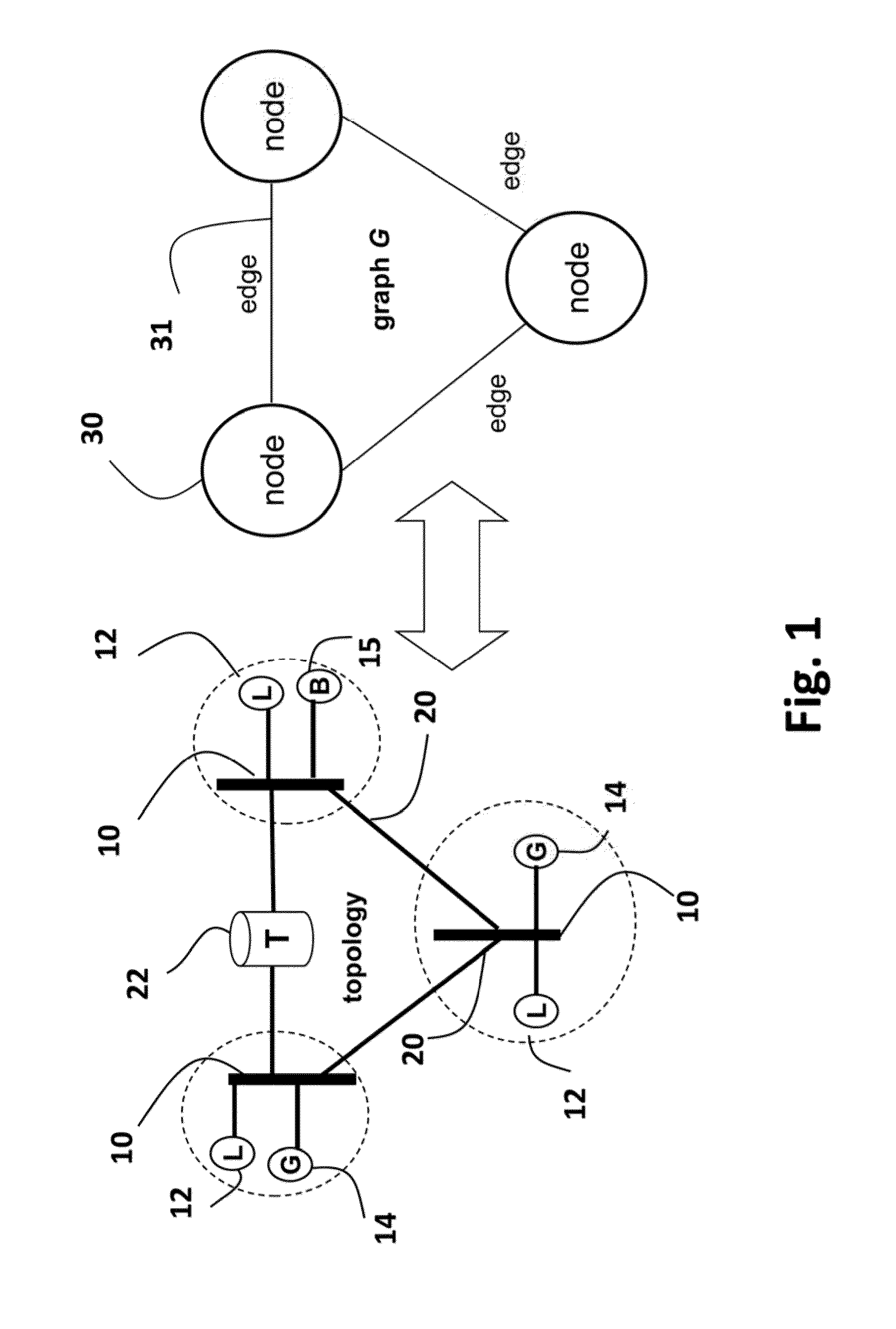
[0026]FIG. 1 shows a topology of an electric power network that can use embodiments of the invention. The network can include AC components, and DC components connected by convertors. The only requirement is that variables and constraints that control the operation of the network are continuously controllable.

[0027]The network includes buses 10 locally connected to loads (L) 12 and generators (G) 14. Additionally, buses are also locally connected to storage devices (B) 15 such as batteries. The buses are interconnected by transmission lines 20. Some of the transmission lines can be connected to transformers (T) 22.

[0028]The generators supply active power (measured in, e.g., Mega Watts (MW)), and reactive power (measured in Mega Volt Ampere Reactive (MVar)). The loads consume the power. The power is defined by voltage magnitude and phase angle.

[0029]The parameters for the optimization include, but are not limited to, an admitt...


PUM


Abstract

Power flow in an electric power network is optimized during multiple time periods of operation of the electric power network by solving an optimization problem represented by an objective function by first initializing variables and constraints of a branch and bound (BB) tree, wherein nodes in the BB tree represent feasible regions of the optimization problem. Upper and lower bounds on the objective function are solved using the BB tree. A lowest upper bound and a lowest upper bound are updated. If difference between the lowest lower bound and the lowest upper bound is less than a threshold, the power flow is outputted based on the lowest lower bound and the lowest upper bound.

Description

FIELD OF THE INVENTION[0001]The present invention relates generally to electric power networks, and more particularly to optimizing power flows in the networks including energy storage devices.BACKGROUND OF THE INVENTION[0002]An electric power network includes buses connected to transmission lines. The buses are locally connected to generators and loads. Optimal power flow (OPF) analysis is often used for monitoring and controlling the operation of the network. The power flow depends, in part, on voltage magnitudes and phase angles. Power flows and voltage levels on the buses are optimized by minimizing an objective function subject to constraints, such as the magnitudes, phases, power transferred, generator capacity, thermal losses, and the like.[0003]Most conventional OPF optimizations:[0004]Use simplifying assumptions, such as small differences between phase angles at buses, to reduce quadratic equalities and inequalities to linear equalities and inequalities. However, such assum...

Claims


Application Information

Patent Timeline
Patent Type & Authority Applications(United States)
IPC IPC(8): G06F1/26
CPCG06F1/26G06F17/11H02J3/06H02J2203/20Y02E40/70Y02E60/00Y04S10/50Y04S40/20Y04S20/222Y02B70/3225G06N5/01H02J3/00G06F2119/06
Inventor RAGHUNATHAN, ARVIND U.GOPALAKRISHNAN, AJITNIKOVSKI, DANIEL N.
Owner MITSUBISHI ELECTRIC RES LAB INC
Why Eureka
Try Eureka