
Aircraft engine systems and methods for operating same

Active Publication Date: 2014-08-28
NUOVO PIGNONE SPA
View PDF6 Cites 21 Cited by
  • Summary
  • Abstract
  • Description
  • Claims
  • Application Information

AI Technical Summary

Benefits of technology

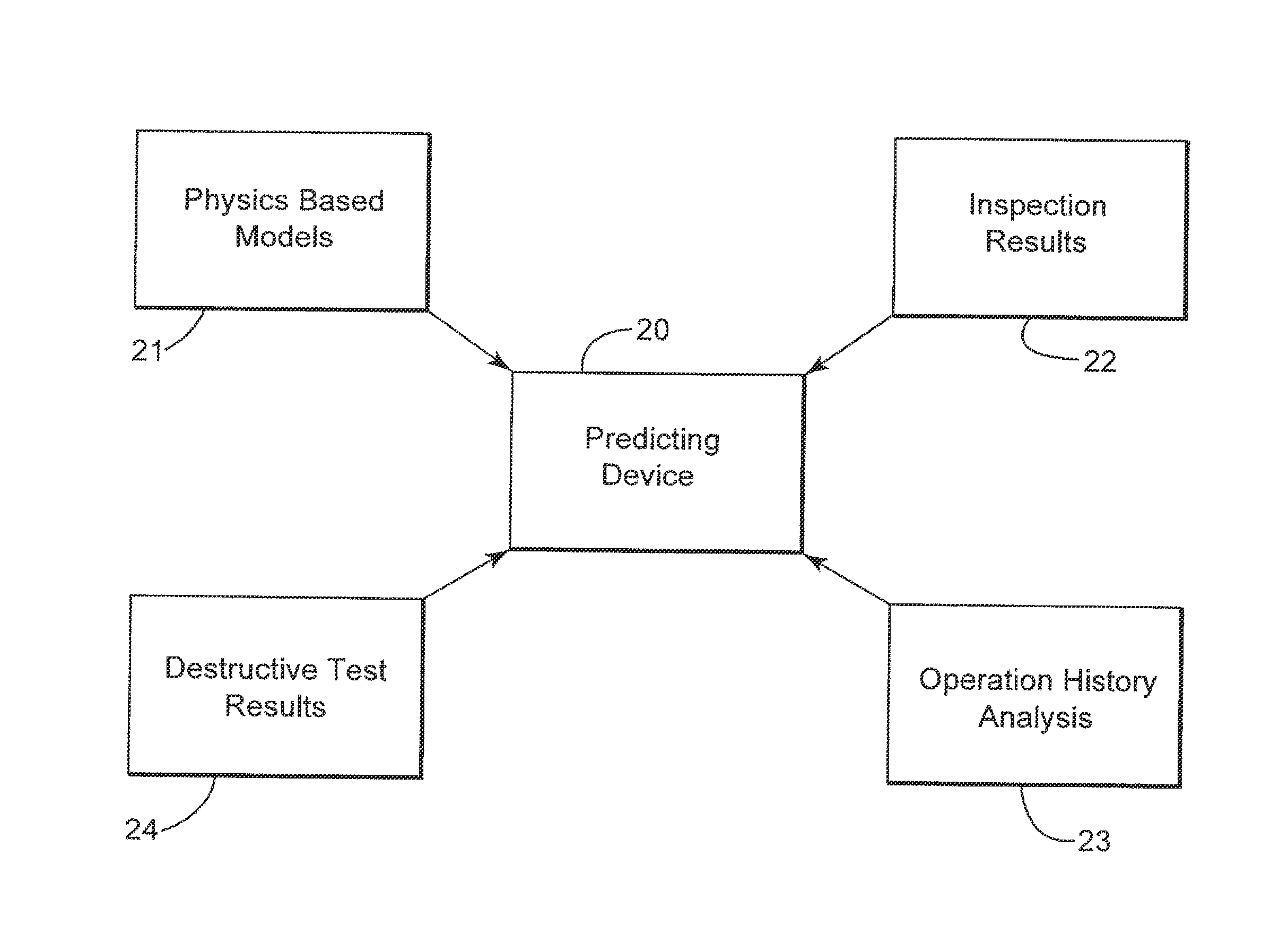
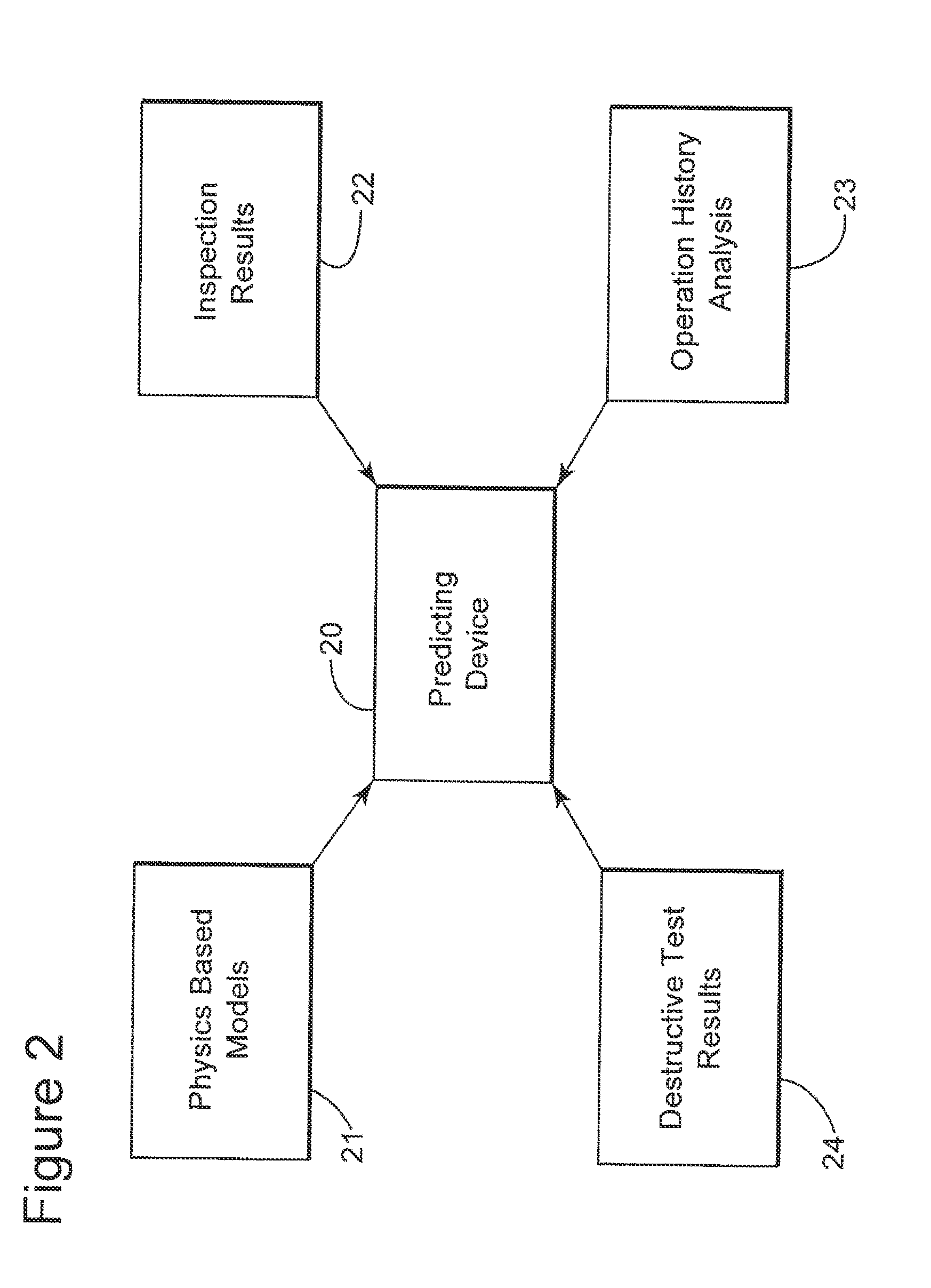
The invention is about a system and method for predicting and optimizing the operating life of gas turbine components, especially those that may not show visible damage but can crack and degenerate quickly due to high thermo-mechanical loads. The method involves receiving operating conditions of the gas turbine and a result of a gas turbine rotor inspection, updating a database for the fleet of gas turFire turbines with the new information, and calculating the residual life expectancy of the rotor based on the information in the database. The invention allows for better maintenance and replacement scheduling, reducing the risk of engine failure and improving plant safety.

Problems solved by technology

However, the conventional methods and systems for plant and turbine life extension require plant shut down for inspections to collect data (e.g., crack lengths) and in general are not applicable for components that do not show evident failure.

Method used


Image

  • Aircraft engine systems and methods for operating same
  • Aircraft engine systems and methods for operating same
  • Aircraft engine systems and methods for operating same

Examples


Embodiment Construction

[0018]The following description of the exemplary embodiments refers to the accompanying drawings. The same reference numbers in different drawings identify the same or similar elements. The following detailed description does not limit the invention. Instead, the scope of the invention is defined by the appended claims. The following embodiments are discussed, for simplicity, with regard to the terminology and structure of a gas turbine, in particularly to a rotor. However, the embodiments to be discussed next are not limited to these systems, but may be applied to other systems.

[0019]Reference throughout the specification to “one embodiment” or “an embodiment” means that a particular feature, structure, or characteristic described in connection with an embodiment is included in at least one embodiment of the subject matter disclosed. Thus, the appearance of the phrases “in one embodiment” or “in an embodiment” in various places throughout the specification is not necessarily referr...


PUM


Abstract

A device and a method for determining a residual life expectancy of a rotor of a gas turbine. The method includes receiving at a computer operating conditions of the gas turbine, receiving a gas turbine rotor inspection result, updating, based on the operating conditions of the gas turbine and the gas turbine rotor inspection result, a database for a fleet corresponding to the gas turbine, and calculating the residual life expectancy of the rotor of the gas turbine.

Description

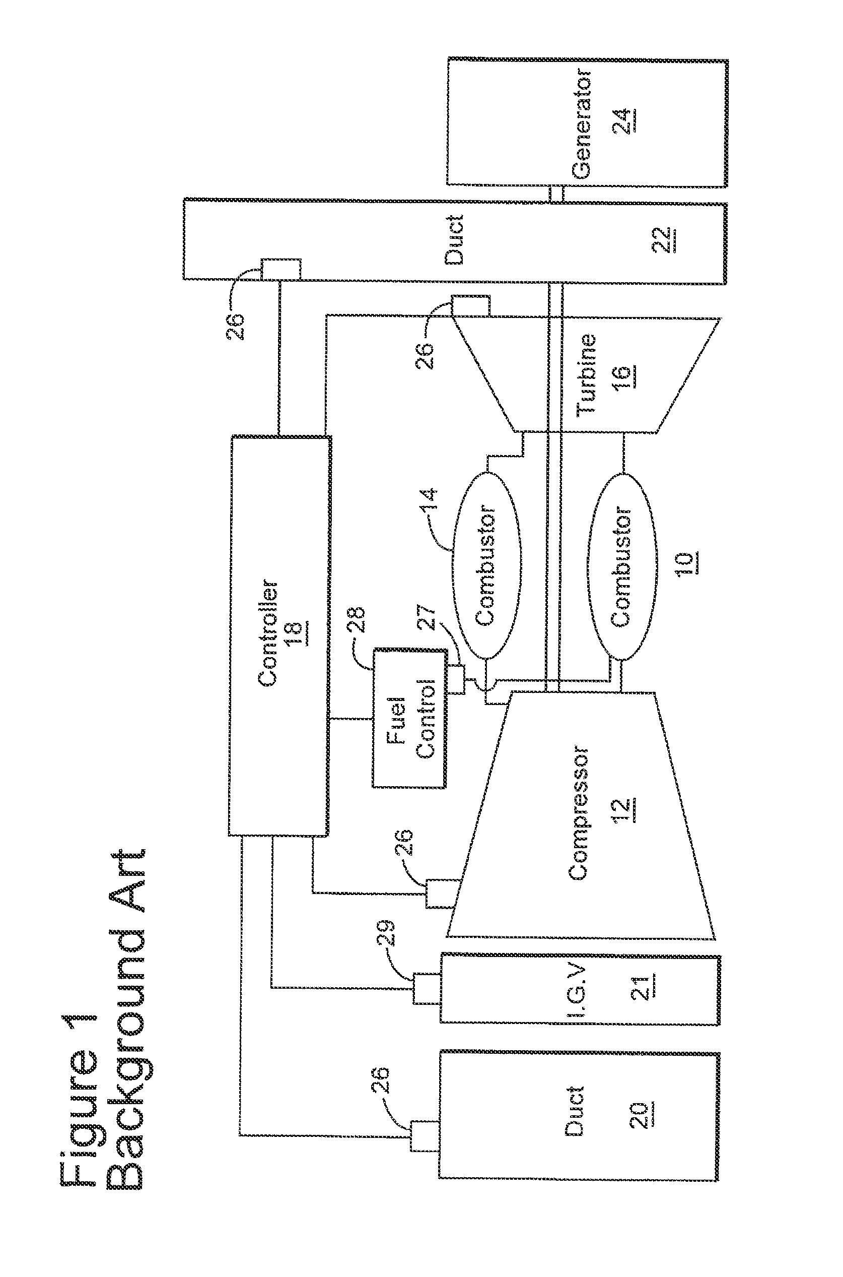
BACKGROUND OF THE INVENTION[0001]Embodiments of the subject matter disclosed herein generally relate to methods and systems and, more particularly, to mechanisms and techniques for predicting and optimizing the operating life of a gas turbine, or components therein.[0002]FIG. 1, which is similar to FIG. 1 of U.S. Patent Application Publication 2008 / 0243352 (incorporated herein by reference), illustrates an example of a gas turbine 10 having a compressor 12, a combustor 14, a turbine 16 coupled to the compressor 12, and a computer control system (controller) 18. An inlet duct 20 to the compressor 12 may feed ambient air to compressor 12. The inlet duct 20 may have ducts, filters, screens and noise abatement devices that contribute to a pressure loss of ambient air flowing through the inlet 20 and into inlet guide vanes 21 of the compressor 12. An exhaust duct 22 for the turbine directs combustion gases from the outlet of the turbine 10 through, for example, emission control and noise...

Claims


Application Information

Patent Timeline
IPC IPC(8): G05B23/02
CPCG05B23/0208G05B23/0283
Inventor DE PROSPERIS, ROBERTODI SISTO, PAOLOBORKOWSKI, MACIEJ
Owner NUOVO PIGNONE SPA
Learn More