Method and system for utilizing heat in a plant or animal growing device, and greenhouse

a technology for growing devices and greenhouses, which is applied in the field of methods and systems for utilizing heat in plants or animals growing devices, and greenhouses, can solve the problems that the devices described above do not use the energy of the heat source in an optimal manner, and achieve the effects of less heat being thrown, and reducing the amount of hea

Active Publication Date: 2014-09-04
SUNDROP FARMS PORT AUGUSTA PTY LTD
View PDF28 Cites 7 Cited by
  • Summary
  • Abstract
  • Description
  • Claims
  • Application Information

AI Technical Summary

Benefits of technology

[0005]According to an example embodiment of a method and device of the present invention, by adding at least one additional heat user in a serial arrangement of the heat users, it becomes possible to arrange the heat users in such a manner that the heat transfer fluid arriving at them has a temperature within an efficient operating range of each of the heat users, without having to dump or otherwise degrade, or diminish, the usability of the heat in the heat transfer fluid. As a result, the method offers a more efficient use of the heat from the heat source in that, for example, the heat in the heat transfer fluid can be used more efficiently, i.e. less heat can be thrown away (to the environment) or reduced in quality or usability by mixing it with colder fluids. This may be understood, for example, by comparing the serial arrangement to a parallel arrangement of the heat users: in a serial arrangement, the full temperature difference, or, in an analogy to an electrical circuit, the full heat “potential”, is used for each heat user, although most heat users will operate only in their most efficient manner when operated at a subrange of said full temperature difference. By arranging the heat users serially, and in an appropriate order, they optimally use the heat in the fluid. This includes optimal use of the exergy, i.e., the amount of energy that can be withdrawn from the heat transfer fluid with respect to the conditions (such as temperature, pressure, electrical potential) of the environment it operates in. Advantageously, a thermal desalination device may allow such an optimal arrangement with a number of other heat users. Heating by the fluid is to be understood to include, in particular, flowing the fluid through the component as well as flowing the fluid through a heat exchanger that is thermally connected to the component.
[0006]Further, since more efficient use is made of the heat source, a smaller heat source will suffice. As a result, lower investment costs become possible for a device that has the same growing capacity.
[0012]In another embodiment according to a method and device of the present invention, at least part of the heat in the circuit is temporarily stored in a heat buffer and then used in at least one of the heat users. This may be particularly useful when one or more heat users temporarily do not need any heat; the heat from the heat source, or from another heat user upstream from the specific heat user(s) temporarily not used, or used at a reduced power, may then be stored until it is needed. Moreover, by using a buffer, temporary peak demands from a heat user may be accommodated for. This provides a method that is more efficient than when a heat user is simply by-passed.
[0016]In a further embodiment according to a method and device of the present invention, in a greenhouse, a serial arrangement of a thermal desalination device with other heat users, in particular the heating of the air in the greenhouse and possibly an organic rankine cycle and / or a salt production device, make a high energy efficiency possible. Moreover, it becomes possible to obtain a lower cost price of the system.

Problems solved by technology

The method and device described above do not use the energy of the heat source in an optimal manner.

Method used


Image

  • Method and system for utilizing heat in a plant or animal growing device, and greenhouse
  • Method and system for utilizing heat in a plant or animal growing device, and greenhouse
  • Method and system for utilizing heat in a plant or animal growing device, and greenhouse

Examples


Embodiment Construction

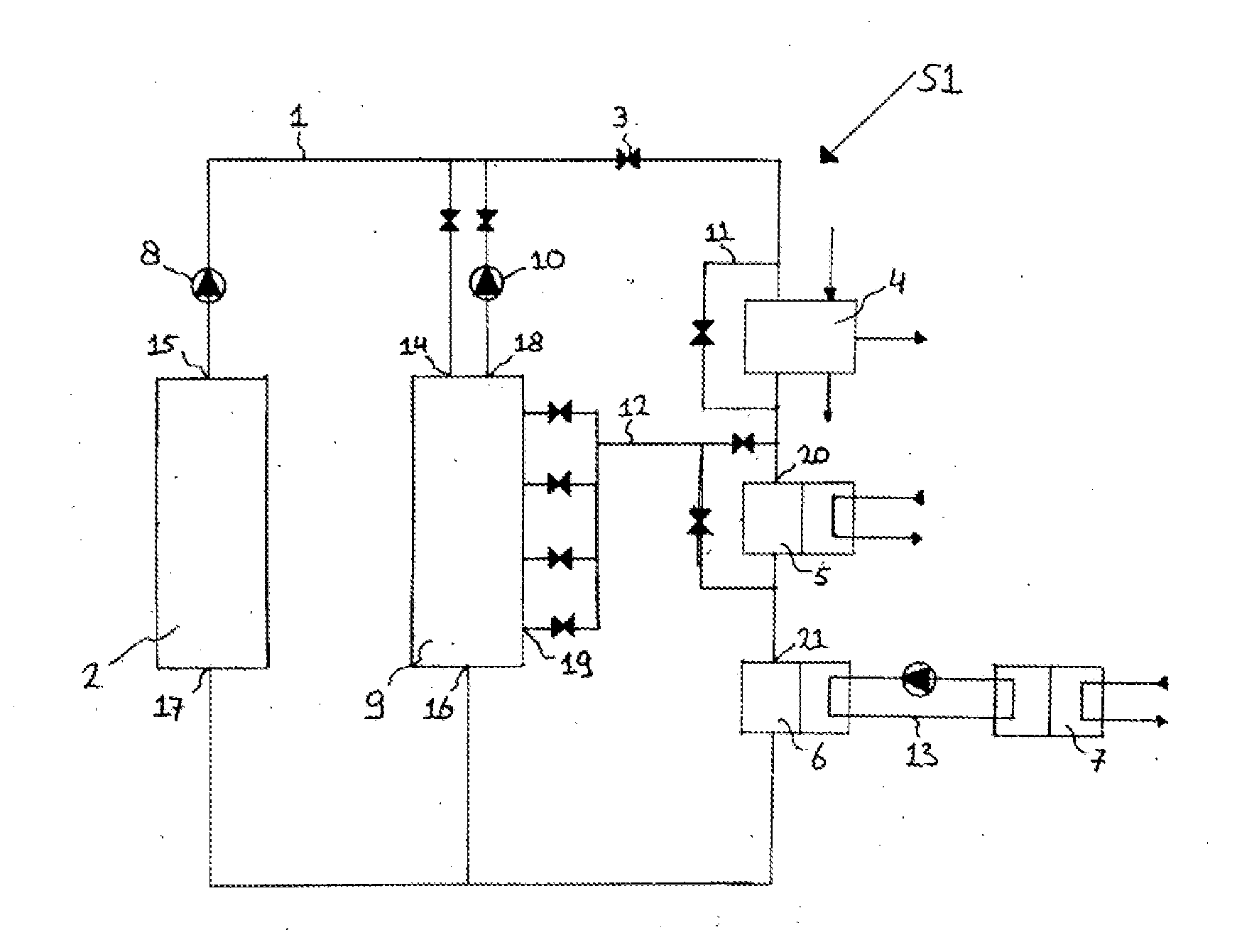
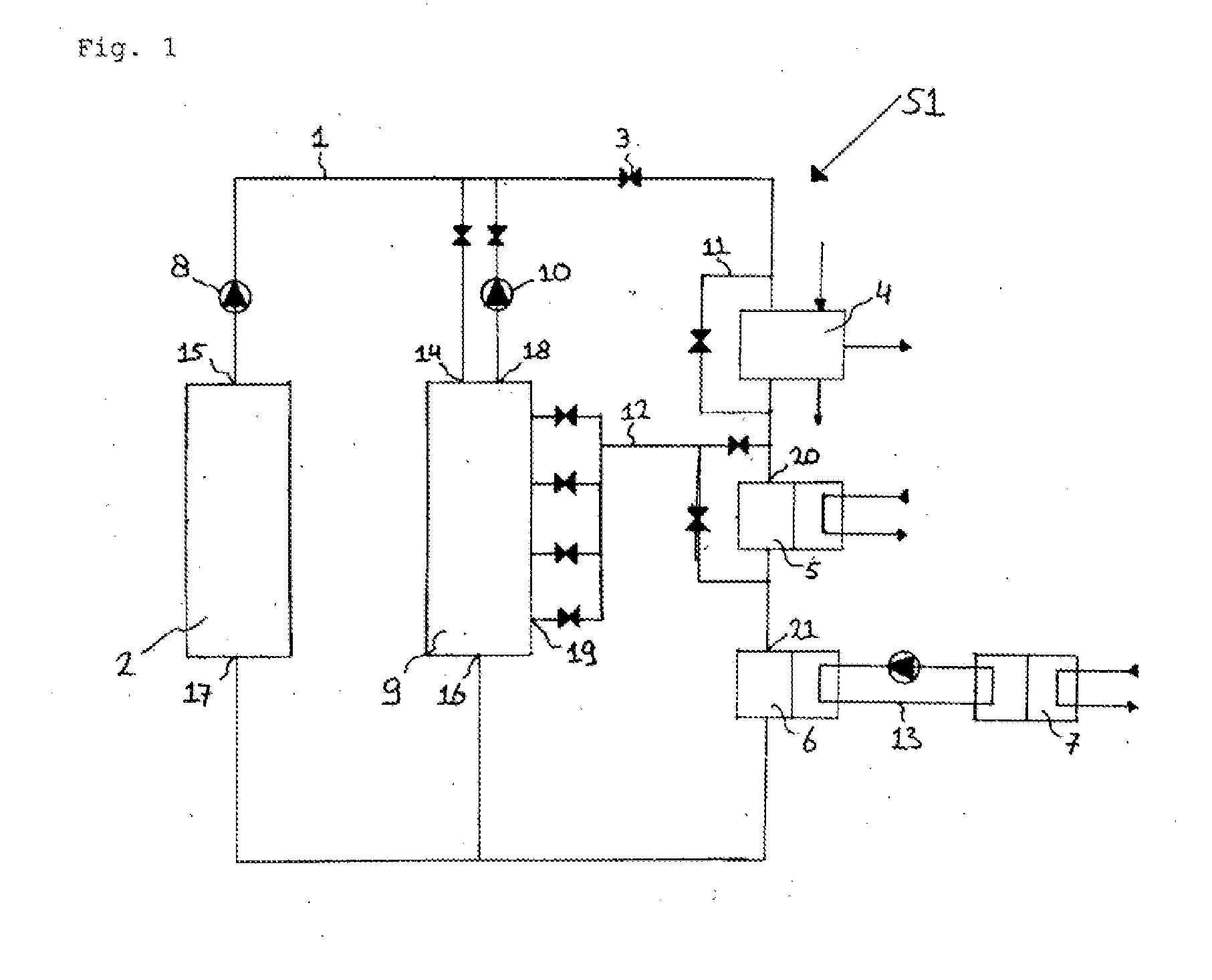
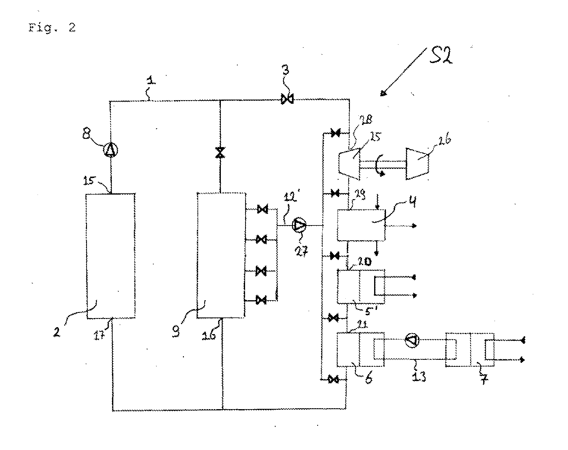
[0020]An exemplary embodiment of a system S1, S2 which is part of a greenhouse for growing plants of the present invention is described with reference to FIGS. 1 and 2.

[0021]The system S1 includes tubes, or piping, 1 represented by lines. The system S1 also contains a solar collector 2 that makes use of optical mirrors (not shown) to concentrate incident solar rays on a fluid line, and as such, to heat the fluid in the fluid line of the solar collector. The solar collector 2 is part of a fluid loop which includes the tubes 1, valves 3, a thermal desalination unit 4, a salt production unit 5, a heat exchanger 6 for a greenhouse air space heating 7 and an electrical pump 8. Arranged parallel to the line with the solar collector 2 and the pump 8 is a line with a heat buffer tank 9 and a pump 10. Line 11 is a bypass line for the thermal desalination unit 4. Line 12, between the buffer tank 9 and the salt production unit 5, connect the buffer tank 9 with the salt production unit 5 and th...


PUM


Abstract

A method for utilizing heat in a plant or animal growing device includes circulating a heat transfer fluid through a circuit forming a closed fluid loop, heating the heat transfer fluid by a heat source, supplying heat from the heat transfer fluid to a first heat user which may be a thermal desalination unit, and returning at least part of the heat transfer fluid that has been cooled down. The heat transfer fluid supplies heat to at least one additional heat user serially arranged before or after the thermal desalination unit. The temperature ranges of the heat transfer fluid are within the optimal operating temperature ranges of the respective heat users in the fluid circuit. A corresponding system and greenhouse by which the method of the invention may be implemented is also described.

Description

FIELD OF INVENTION[0001]The present invention relates to a method and system for utilizing heat in a plant or animal growing device, and a greenhouse.BACKGROUND INFORMATION[0002]Plant or animal growing devices, such as greenhouses, and artificial water ponds for growing fish and cattle farms, are in use all over the world. In such devices, energy in the form of heat is used by several heat users, such as a heating unit, that serves to provide an adequate temperature of the medium in which the specific type of plant or animal grows (typically air or water). The heat source may obtain its energy in any manner, typically by burning fossil fuel or by catching solar power. The heat users may vary according to the geographical circumstances, such as the availability of fresh water or seawater. For example, one of the heat users may be a thermal desalination unit, in locations where seawater is abundant and fresh water is scarce.[0003]European Patent No. EP 1 071 317 describes a greenhouse...

Claims


Application Information

Patent Timeline
Patent Type & Authority Applications(United States)
IPC IPC(8): A01G9/14
CPCA01G9/14A01G9/243A01G25/167A01K1/0076A01K63/065F24D3/005Y02A40/25Y02P60/12A01G9/245C02F1/14C02F2103/08
Inventor SAUMWEBER, PHILIPPWOLTERBEEK, REINIER RUDY
Owner SUNDROP FARMS PORT AUGUSTA PTY LTD
Why Eureka
Try Eureka