Permanent magnet electrical machine

a permanent magnet and electrical machine technology, applied in the direction of dynamo-electric machines, synchronous machines with stationary armatures and rotating magnets, electrical apparatus, etc., can solve the problems of distorted voltage and current waveforms, increased cost, poor voltage regulation

Active Publication Date: 2014-09-04
RADIAL FLUX LAB
View PDF6 Cites 9 Cited by
  • Summary
  • Abstract
  • Description
  • Claims
  • Application Information

AI Technical Summary

Problems solved by technology

They use relatively high volumes of magnetic material that increases their cost.
When operated as synchronous generators they have poor voltage regulation and can suffer from distorted voltage and current waveforms under load.
When operated as synchronous motors they are difficult to start without some form of sensor feedback.
Also, their (stator) back emf waveforms under load are distorted, reducing their efficiency and requiring more complex control electronics.
These problems are greater with low pole number (e.g., 2- and 4-pole) machines, where serious waveform distortion under load commonly occurs.
The distortion arises due to the so-called flux drag effect that causes the magnetic flux in the rotor to skew away from the radial axis of the magnets due to the load current in the windings.
Accordingly, PM synchronous generators have not found widespread use in small-scale power applications, such as single-phase and, three-phase 3000 rpm (2-pole) or 1500 rpm (4-pole) petrol and diesel driven generators in the 5 to 20 kW range.
However, these also have distorted output voltage / back emf and current waveforms under load, and can suffer from demagnetization of the magnet edges under high loads.
Surface-mounted magnet segments for 2-pole and 4-pole rotors have a large arc segment, meaning there is a large amount of waste material in their manufacture, increasing the monetary cost of the magnets.
Current designs of surface-mount PM AC generators exhibit a large voltage drop under load.
As there is no simple method of voltage regulation at constant speed for these machines, generator applications requiring good voltage regulation, cannot use PM synchronous types.
The main problem with these designs is that they use up to six times or more magnet material than the equivalent surface-mount designs, even in the lower powers, and cannot be made in a 4-pole configuration.
Rather, such machines are only practical in 2-pole designs up to 3 kW power rating.
Above this level the magnet cost and volume increases to the square of the rotor diameter, making them no longer cost-effective.
These problems mean that current designs of PM generators and motors are suitable only for low-grade, low power applications where voltage regulation (i.e., generators) or back emf (i.e., motors), and harmonic distortion are unimportant.

Method used


Image

  • Permanent magnet electrical machine
  • Permanent magnet electrical machine
  • Permanent magnet electrical machine

Examples


Embodiment Construction

[0024]In what follows, reference to “an electrical machine” (or simply “a machine”) is to be understood as applying equally to a machine configured and / or operated as a generator or motor, unless specifically indicated as being otherwise.

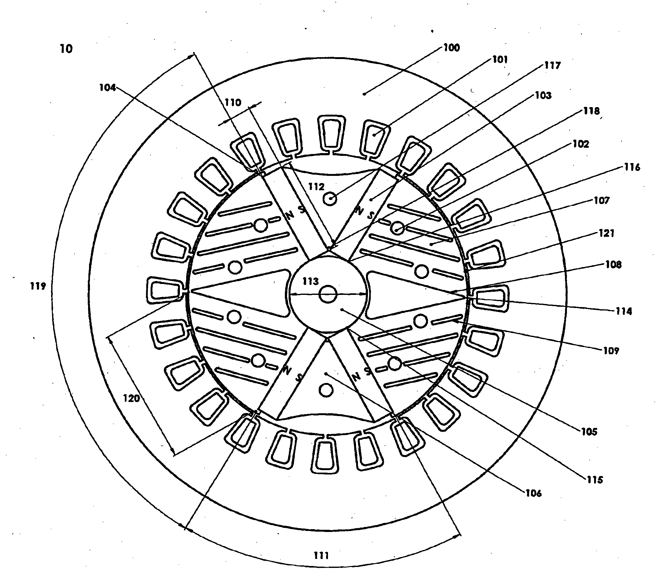
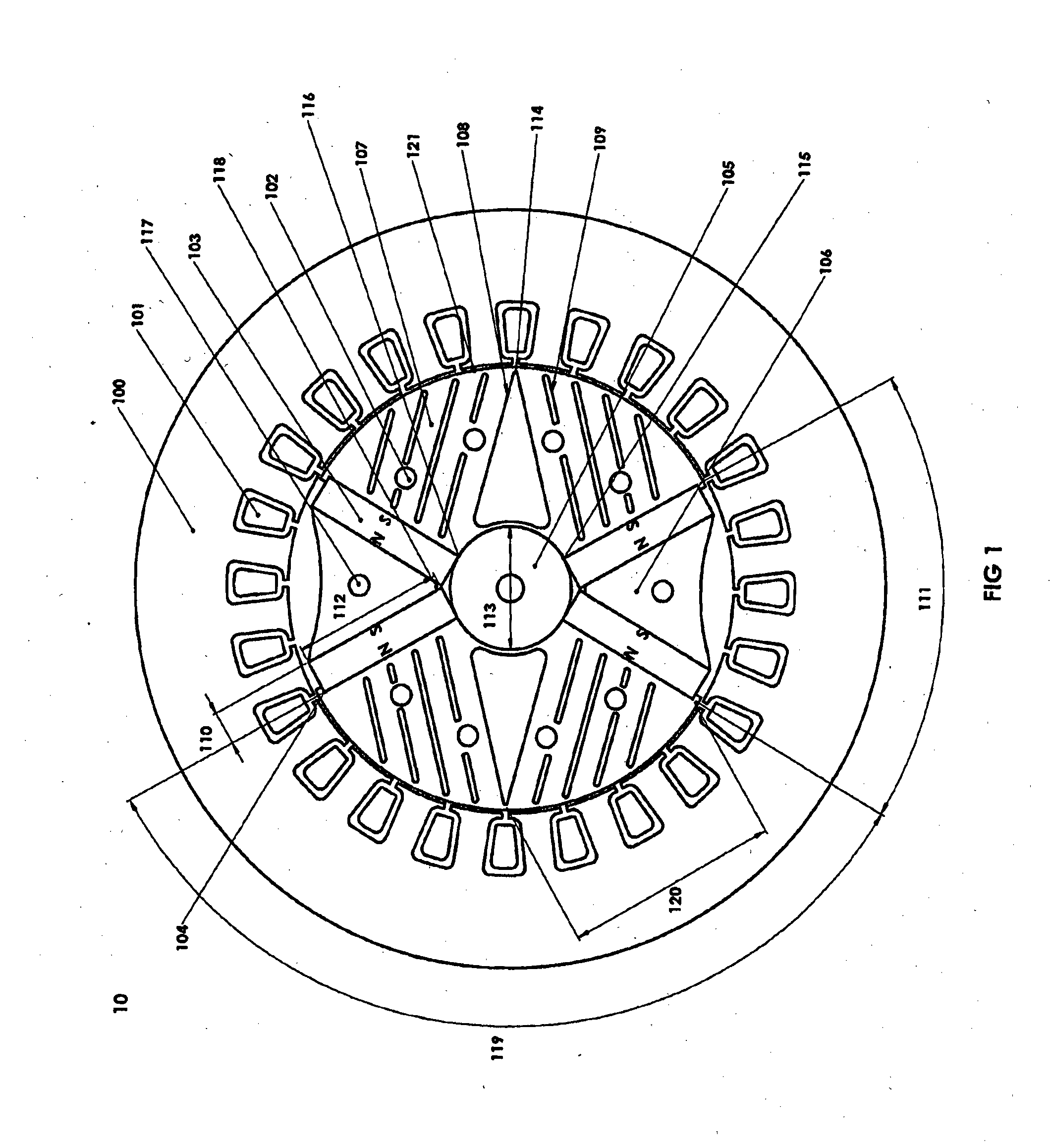
[0025]FIG. 1 shows, in cross-section, a 2-pole machine arrangement 10 embodying the invention. The stator 100 has windings 101 in conventional form, wound either in a single phase or three phase configuration. The rotor is formed of stacked laminations. The number of such laminations determines the power output of the machine. The laminations are clamped together by rods (not shown in FIG. 1) passing through the spaced holes 102 and 117, and secured at either end-most lamination, typically using end plates (not shown). A typical rotor diameter for a 5 to 20 kW machine is in the range 100 mm to 130 mm. The laminations include rotor pole pieces 107 located between the two magnetic poles. Each pole is formed by a pair of (embedded) permanent magnets 10...


PUM


Abstract

A 2-pole machine arrangement (10) has a stator (100) with windings (101) in conventional form, wound either in a single phase or three phase configuration. The rotor is formed of stacked laminations. The laminations include rotor pole pieces (107) located between the two magnetic poles. Each pole is formed by a pair of (embedded) permanent magnets (103), angularly spaced-apart by inter-magnet segments (106). The rotor pole pieces (107) include a series of evenly-spaced slots (109) and a central void (108). The slots (109) are of various lengths to direct the flux from the magnets (103) into the air gap (121) at a desired angle normal to the rotor surface. The slots 109 may be varied in width and angle to achieve the desired lowest waveform distortion under load and the highest air gap flux. The slots (109) also contribute to changing the saliency of the rotor.

Description

TECHNICAL FIELD[0001]This invention relates generally to a permanent magnet (PM) electrical machine operating either as a synchronous generator or a synchronous motor. More particularly, the invention relates to the control of harmonic components in the output / stator voltage and current waveforms under load.BACKGROUND[0002]PM synchronous machines are robust, reliable and efficient, and have a relatively high energy density. They have many attractive properties compared with wound-field synchronous machines with brushed or brushless exciters. The need to save energy and increase the efficiency of motors and generators means PM synchronous machines are becoming a popular candidate because of their no-loss rotors. In some cases an energy saving of up to 20% can be achieved by using PM rotors in place of wound rotors.[0003]Despite these advantages, some current designs of PM synchronous machines have shortcomings. They use relatively high volumes of magnetic material that increases thei...

Claims


Application Information

Patent Timeline
Patent Type & Authority Applications(United States)
IPC IPC(8): H02K1/27
CPCH02K1/27H02K1/2746H02K1/28H02K2213/12
Inventor LILLINGTON, PAUL EVAN
Owner RADIAL FLUX LAB
Why Eureka
Try Eureka