Converters

Active Publication Date: 2014-09-04
GE ENERGY POWER CONVERSION TECH
View PDF19 Cites 61 Cited by
  • Summary
  • Abstract
  • Description
  • Claims
  • Application Information

AI Technical Summary

Benefits of technology

[0037]As is the case for a conventional LCC, the AC line current may be drawn at a power factor that is less than unity. Increases in phase control angles, i.e., firing advance angle β and firing delay angle α, cause a reduction in power factor and therefore, modes (b) and (c) allow reductions in both phase control angles. The AC line commutating reactance also has an influence upon power factor in as much as it is responsible for the phase lag in AC line current that is associated with inverter and rectifier commutation overlap angles μ and γ, respectively, but the effect of commutating reactance upon voltage regulation is of greater significance.
[0038]Although the above-described reduced phase control angles upon AC grid-side harmonics is significant, the use of series mode active filters to reduce DC line ripple voltage and current opposes this effect and the combined effects of the above-described aspects of DC line filtration may cause the total harmonic distortion of AC line current harmonics to be worsened relative to that of a conventional LCC. Accordingly, the AC line current may optionally use power factor correction and filtration equipment connected to the AC lines on the AC grid-side of the converter transformer. This equipment may be of any convenient type and the use of shunt mode voltage source converter type static

Problems solved by technology

If the forward recovery process is not complete before the end of the available circuit commutated turn-off time, then anode current will flo

Method used


Image

  • Converters
  • Converters
  • Converters

Examples


Embodiment Construction

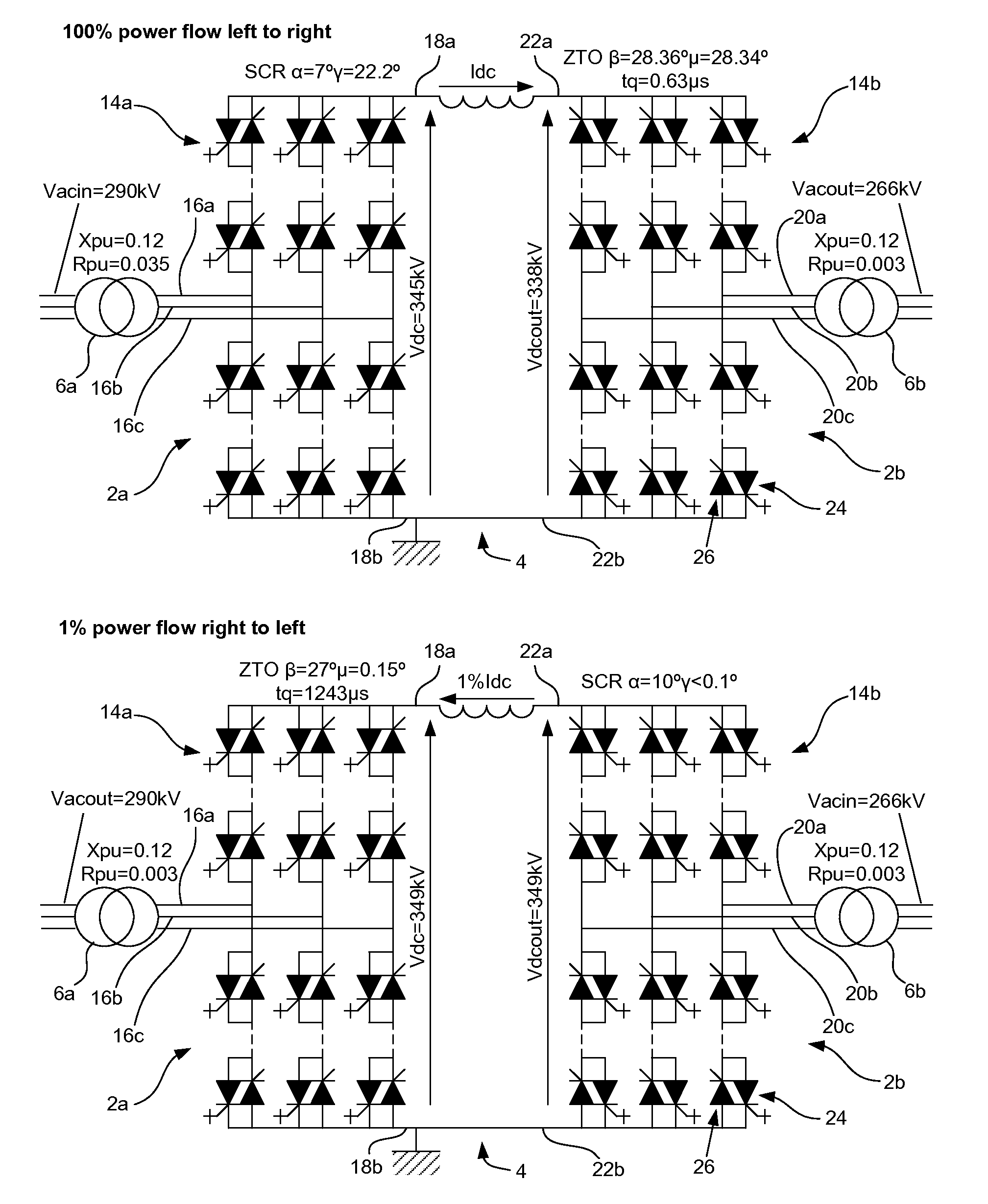
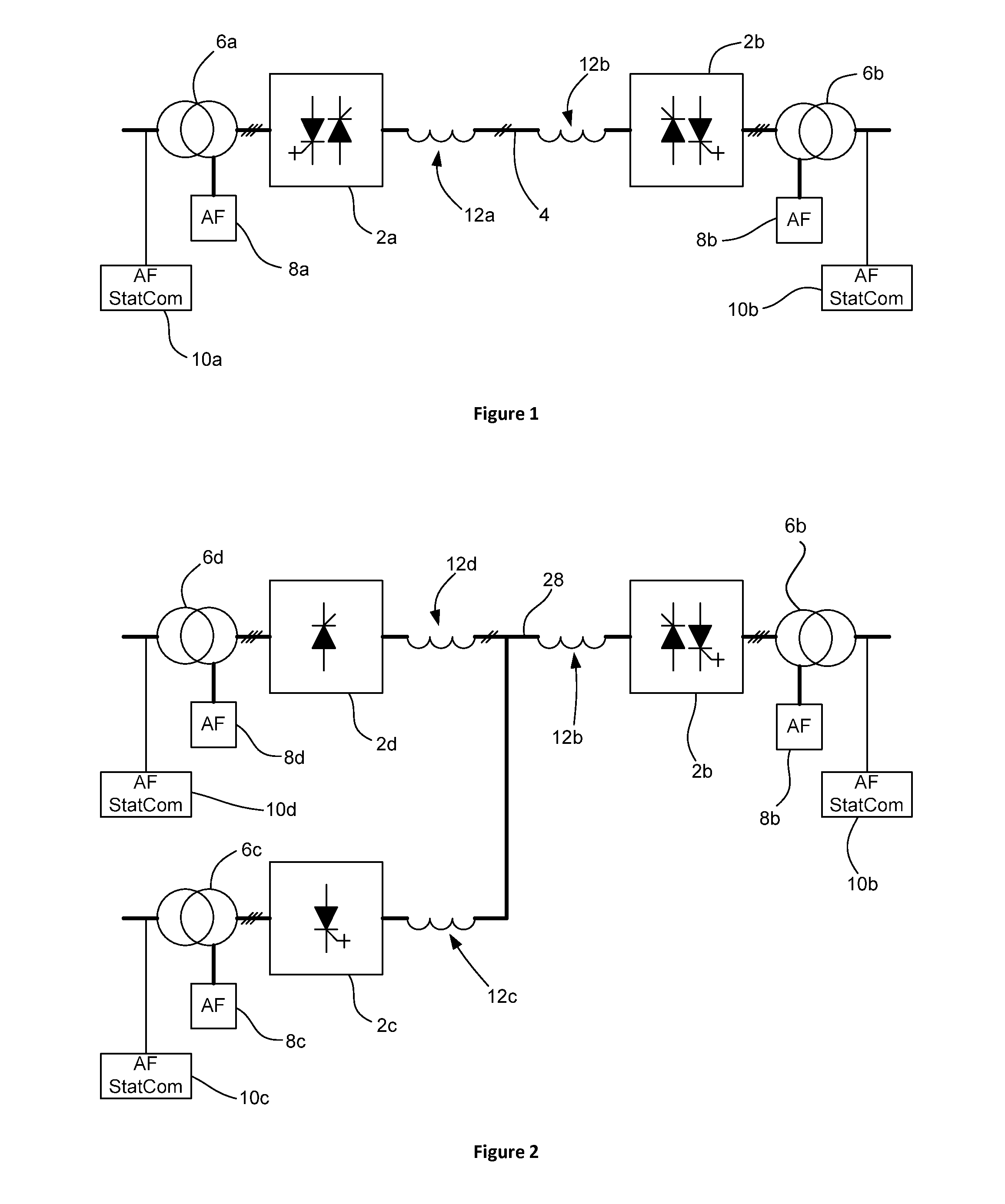
[0050]With reference to FIGS. 1 and 4, a point-to-point HVDC transmission link includes a first current source converter (CSC) 2a and a second CSC 2b connected to first and second respective ends of an HVDC transmission line 4. Each CSC 2a, 2b is shown as being a three-phase transformer-fed type with an associated converter transformer 6a, 6b, a series mode voltage source active filter (AF) 8a, 8b, a shunt mode combined active filter and static compensator (AF StatCom) 10a, 10b, and a DC link inductor 12a, 12b. Surge arresters and the control system are not shown in FIGS. 1 and 4 for reasons of clarity. Active filters and filter compensators are not shown in FIG. 4 for reasons of clarity.

[0051]With particular reference to FIG. 4, each CSC 2a, 2b includes a bridge 14a, 14b. The first bridge 14a has three AC terminals 16a, 16b, 16c (i.e., one for each phase) connected to the associated converter transformer 6a and two DC terminals 18a, 18b connected to one end of the HVDC transmission...


PUM


Abstract

A converter, and in particular a current source converter, including a bridge having an AC terminal for each of one or more AC lines, and first and second DC terminals. A converter arm is connected between each respective AC terminal and the first DC terminal, and between each respective AC terminal and the second DC terminal. Each converter arm includes a first power semiconductor switching device capable of being turned ‘on’ and ‘off’ by gate control and having a recovery time. The converter is adapted to be operated in one or more inverting modes.

Description

TECHNICAL FIELD[0001]Embodiments of the present invention relate to converters, and in particular to current source converters (CSCs) for use inter alia in high voltage direct current (HVDC) point-to-point transmission links and HVDC multi-terminal grids where maximum power conversion efficiency and availability are required.BACKGROUND ART[0002]Line commutated converters (LCC) are a type of current source converter (CSC) and can be employed in high voltage direct current (HVDC) transmission links between high voltage alternating current (HVAC) power networks or grids. LCCs employ naturally commutated thyristor bridges in rectifying (power transmitting) and inverting (power receiving) terminals. Power flow through such HVDC transmission links may be reversible whilst HVDC transmission current is unipolar. HVDC transmission link voltage must also be reversible and this can be achieved using the well known principle of phase control. The requirement for a reversible HVDC transmission l...

Claims


Application Information

Patent Timeline
IPC IPC(8): H02J3/36
CPCH02J3/36H02M1/08H02M7/5152H02M7/521
Inventor CRANE, ALLAN DAVIDBLEWITT, WARREN MARK
Owner GE ENERGY POWER CONVERSION TECH
Why Eureka
Try Eureka