Hill Start in a Vehicle

a technology of automatic braking and start-up, which is applied in the direction of braking systems, analogue processes for specific applications, instruments, etc., can solve the problems of undue wear on the brakes, undue wear on the drive train components such as the torque converter, and achieve the effect of reducing the braking for

Inactive Publication Date: 2014-09-04
CATERPILLAR INC
View PDF9 Cites 8 Cited by
  • Summary
  • Abstract
  • Description
  • Claims
  • Application Information

AI Technical Summary

Benefits of technology

[0007]A method of providing a hill brake in a vehicle may include determining that the vehicle is on an incline, determining that the vehicle is stopped, determining that the vehicle is configured for uphill propulsion, and calculating a grade load on the vehicle. The method may also include calculating a braking force approximately equal to the grade load, applying the braking force via a braking system in the vehicle, and sensing release of a brake pedal. The method may continue after sensing release of the brake pedal and until a trigger event is reached by calculating a rimpull at a drive wheel of the vehicle, reducing the braking force corresponding to an increase in rimpull, and upon reaching the trigger event, releasing the braking force.

Problems solved by technology

However, restarting from an incline may cause a challenge for an operator wishing to avoid rolling downhill while accelerating from the stopped position.
The two foot operation, in addition to simply being a nuisance or a distraction to the operator, causes the brakes to be applied over increasing engine torque and may cause undue wear on the brakes, as well as undue wear on drive train components such as a torque converter, gearbox, and / or drive motors.
Lauri, however fails to disclose determining delivered rimpull force at a drive wheel of the vehicle and reducing a braking force proportional to the rimpull.

Method used


Image

  • Hill Start in a Vehicle
  • Hill Start in a Vehicle
  • Hill Start in a Vehicle

Examples


Embodiment Construction

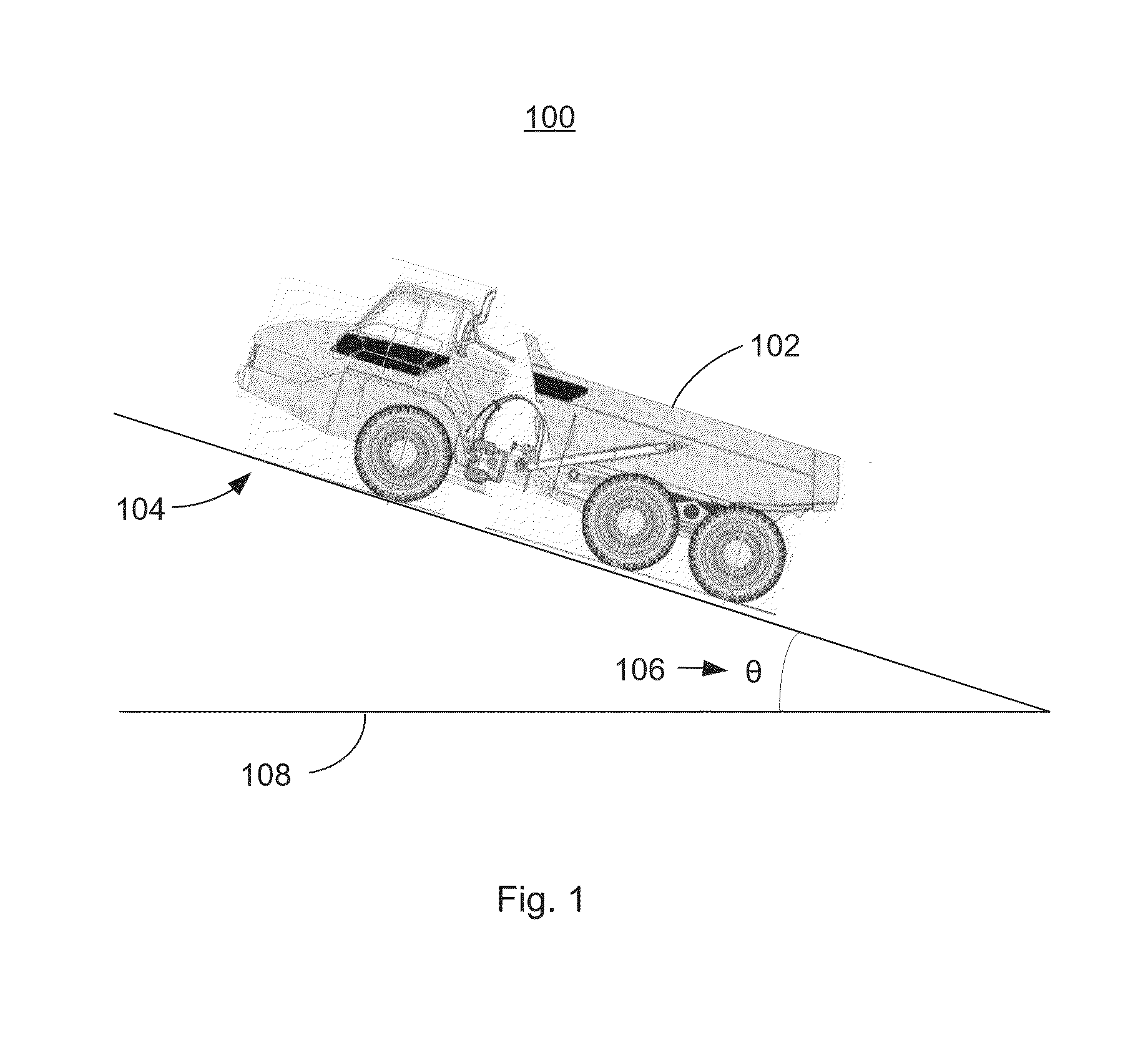
[0012]FIG. 1 is an illustration of a work site 100 showing a vehicle 102 on an incline 104. The incline 104 may be measured by an angle θ106 from a level reference 108. In the illustration, the vehicle 102 is shown facing uphill, that is so that driving in a forward gear causes uphill motion. When discussing a hill brake, it is equally valid that the vehicle 102 may be facing downhill such that driving in a reverse gear causes uphill motion.

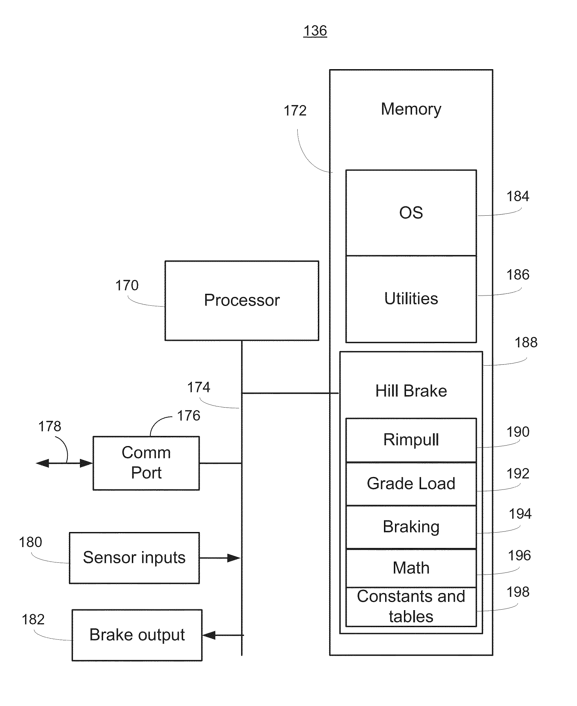
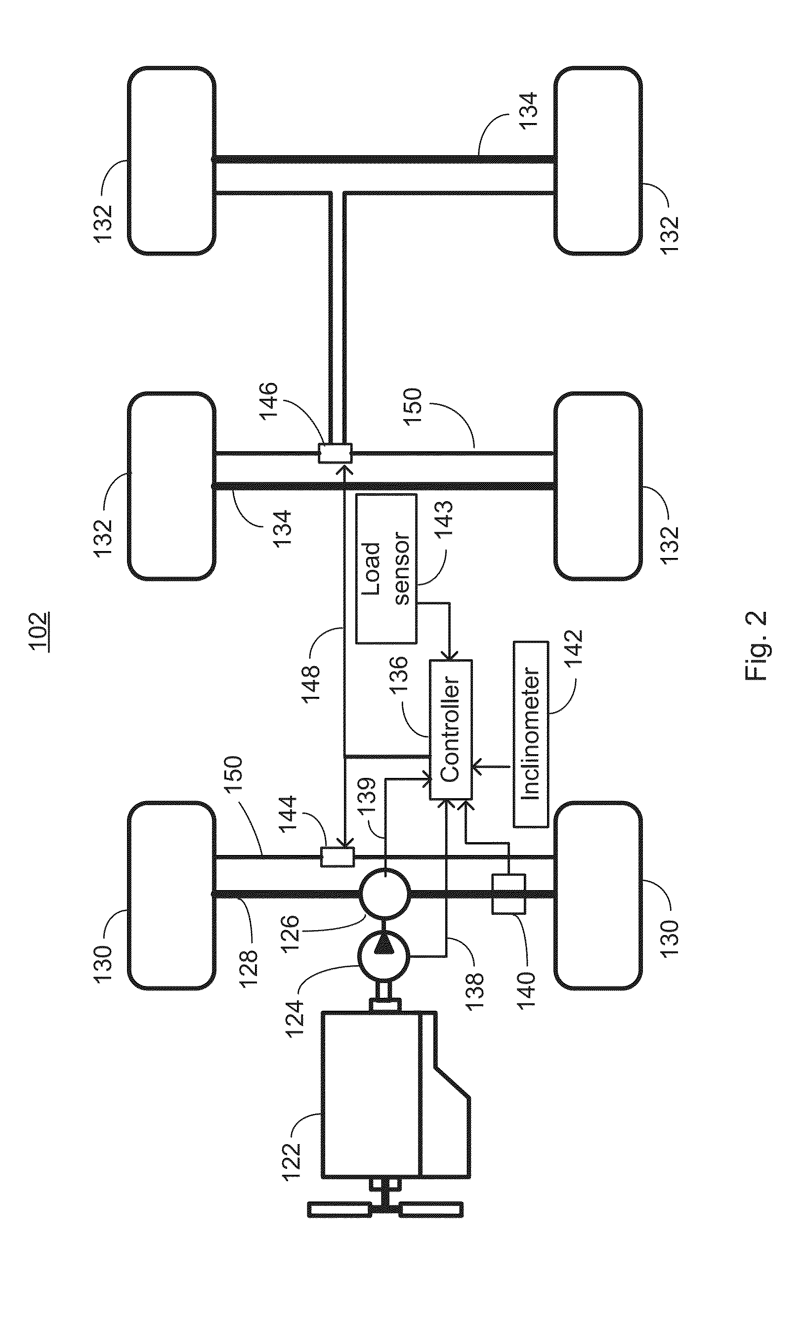
[0013]FIG. 2 is a simplified schematic diagram of the vehicle 102 of FIG. 1 showing components associated with a hill brake system. The vehicle 102 may include an engine 122, coupled to a torque converter 124, whose output drives a transmission 126 and ultimately delivers torque via an axle 128 to drive wheels 130.

[0014]In an embodiment, wheels 132 may be unpowered and may carry a payload bearing element of the vehicle 102. For example, the vehicle 102 may be an articulated truck. In other embodiments, the vehicle 102 may be any of a number of ma...


PUM


Abstract

A hill brake system in a vehicle uses a controller to determine when a number of conditions, such as being stopped on an incline, are met and then automatically applies a braking force at least equal to a calculated grade load, that is, gravitational force. Using drive train measurements and known drivetrain characteristics, a rimpull force is calculated after release of an operator-controlled brake and the automatically applied braking force is reduced corresponding to the rimpull force generated by the drivetrain. The automatically applied braking force is released when any of several conditions are met including uphill motion of the vehicle or expiration of a timeout timer.

Description

TECHNICAL FIELD[0001]The present disclosure relates to an automated braking system for use in preventing downhill motion when starting a vehicle on an incline.BACKGROUND[0002]Heavy equipment, such as large earthmoving vehicles, must often stop on inclines. However, restarting from an incline may cause a challenge for an operator wishing to avoid rolling downhill while accelerating from the stopped position. In many cases, the operator will “two foot” the process, applying the left foot to the brake and the right foot to the accelerator so that the engine torque increases to a point where releasing the brake will not cause downhill motion.[0003]This process, however, has several drawbacks. Unintended motion downhill is one. The two foot operation, in addition to simply being a nuisance or a distraction to the operator, causes the brakes to be applied over increasing engine torque and may cause undue wear on the brakes, as well as undue wear on drive train components such as a torque ...

Claims


Application Information

Patent Timeline
Patent Type & Authority Applications(United States)
IPC IPC(8): B60T7/12
CPCB60T7/12B60T7/122
Inventor SCHWARTZ, TIMOTHY D.LANDES, JAMESWISLEY, DAVID R.MENOLD, RODNEY L.
Owner CATERPILLAR INC
Why Eureka
Try Eureka