
Split collar mountable wind turbine

Active Publication Date: 2014-09-11
LILU ENERGY
View PDF25 Cites 8 Cited by
  • Summary
  • Abstract
  • Description
  • Claims
  • Application Information

AI Technical Summary

Benefits of technology

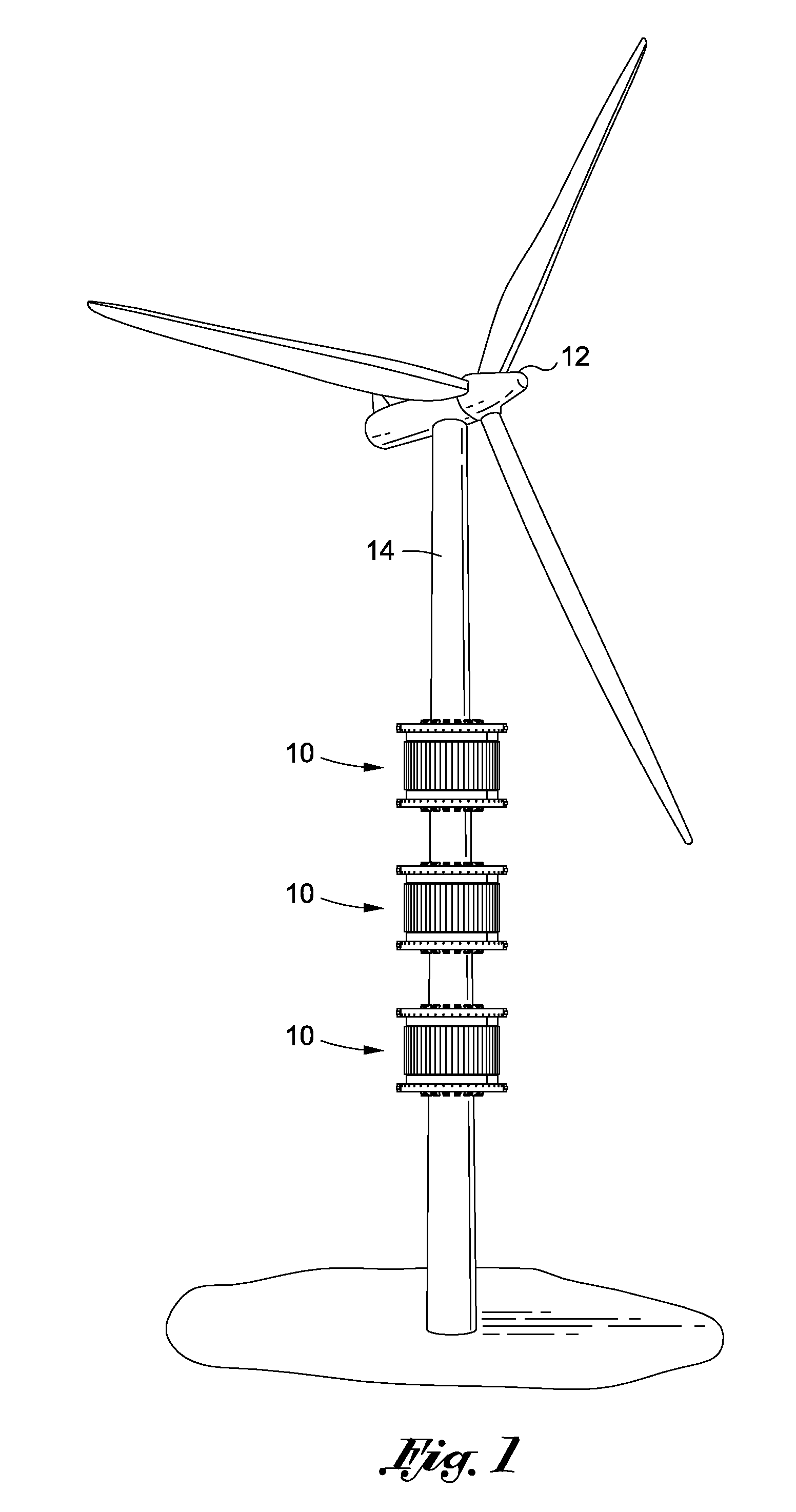
The present invention is a wind turbine that can be attached to existing structures such as light poles, power poles, water towers, and similar structures. This eliminates the need for a separate mast and power grid access, resulting in significant cost savings. Additionally, the wind turbine can provide power to devices associated with the structure, such as traffic lights, communication towers, and battery storage units. The wind turbine uses rare earth magnets, or electro magnets, to reduce friction and provide magnetic levitation of the blade housing. This design also creates its own lift to ease stress on the bottom attachment ring.

Problems solved by technology

Existing devices and methods adapted to harness renewable sources, such as wind power, may have the unwelcome effect of creating large and noticeable physical footprints on existing landscapes.
Wind farms that use existing wind turbines may be located in less densely populated areas and may utilize large tracts of valuable land and many times increase the cost of kilowatt hour due the requirement of construction of access to electrical grids.
Wind generators located in more densely populated areas may block views, block sunlight, create noise and otherwise may be ascetically undesirable.
In addition, existing horizontal and vertical wind turbines can be a danger to certain bird populations.
Because of the length of the blades and the size of propeller, many times such wind turbines are affixed atop very tall masts making maintenance and repair difficult.
Also the installation of the masts are expensive and are required to support a significant amount of weight to support both the blades and generator which is typically located at the center of the blades.
A conventional propeller type wind turbine with blades also typically rotates perpendicular to wind direction requiring expensive mechanisms to rotate either or both of the forward direction of the proper, or the angle of the propeller blades.

Method used


Image

  • Split collar mountable wind turbine
  • Split collar mountable wind turbine
  • Split collar mountable wind turbine

Examples


Embodiment Construction

[0026]The detailed description set forth below in connection with the appended drawings is intended as a description of certain embodiments of the present disclosure, and is not intended to represent the only forms that may be developed or utilized. The description sets forth the various functions in connection with the illustrated embodiments, but it is to be understood, however, that the same or equivalent functions may be accomplished by different embodiments that are also intended to be encompassed within the scope of the present disclosure. It is further understood that the use of relational terms such as first, second, and the like are used solely to distinguish one element from another without necessarily requiring or implying any actual such relationship or order between such elements.

[0027]Existing structures such as light poles, traffic light arms, communication towers, wind turbine masts, chimneys and smoke stacks are commonplace in the modern landscape in both rural and ...


PUM


Abstract

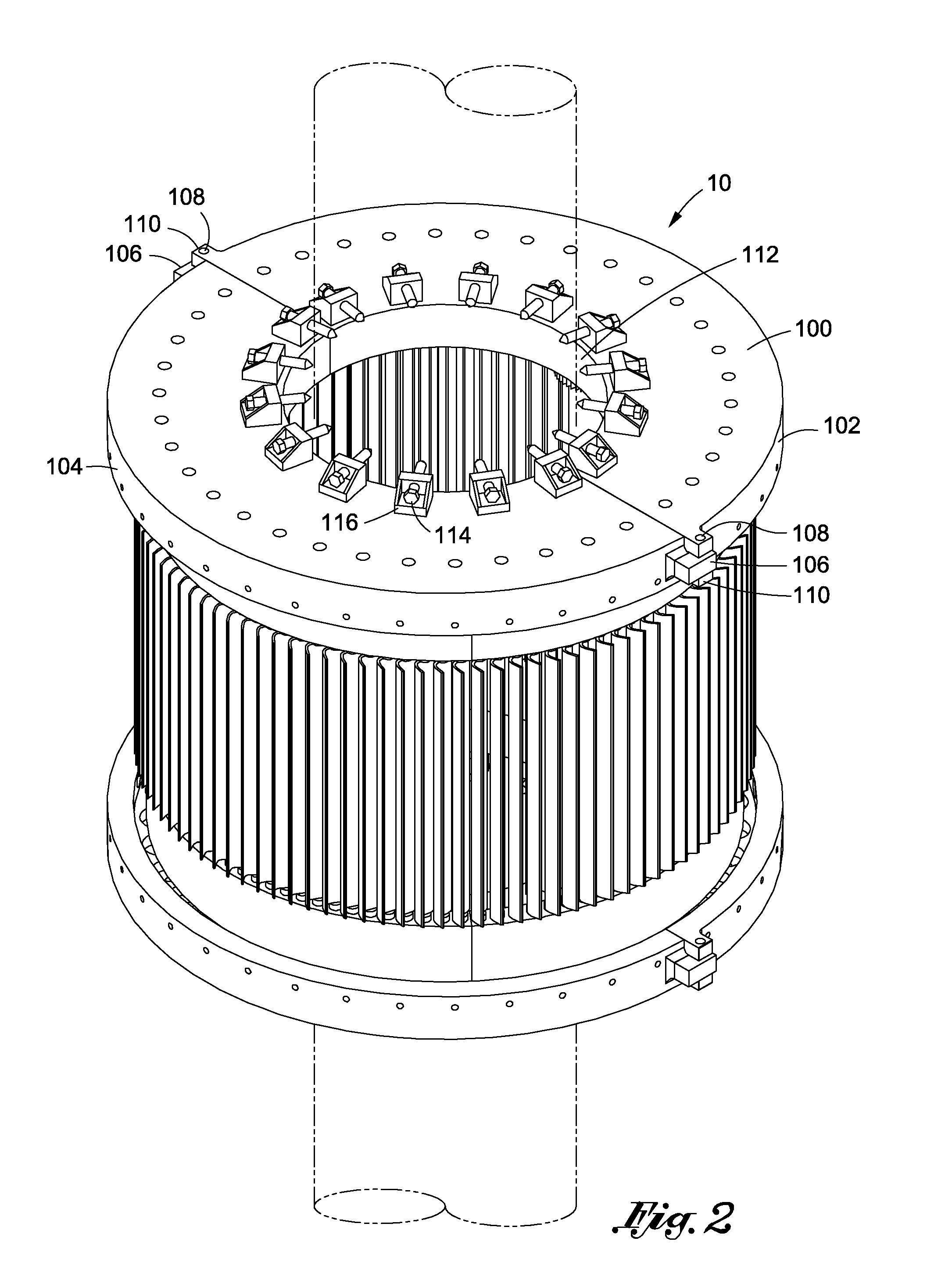
The present invention relates to a split collar mountable turbine that can be assembled in two separate halves and adapted to be attached circumferentially around existing structures such as electrical pole, light poles and traffic poles. Top and bottom attachment rings each comprise first and second arcuate elements adapted to interconnect circumferentially about an axis to form two rings formed in spaced relation. A fan blade housing ring comprising first and second arcuate elements, adapted to interface into complimentary slots within the top and bottom rings, and also adapted to interconnect circumferentially about an axis to form a fan blade housing ring and is received in complimentary slots The fan blade housing ring moves in tracks located in the top and bottom rings by magnetic levitation. Located within the fan blade housing are two pair of off-axis electrical generators each having rotating gears wherein said rotating gears are driven by rotation of said fan blade housing which the drives the generators in order for the generator to produce electricity. A series of set screws and set guides affixed to the top and bottom rings can be adjusted to engage and be supported by a structure that is collared in the open center of the cylindrical wind turbine.

Description

CROSS-REFERENCE TO RELATED APPLICATIONS[0001]Not ApplicableSTATEMENT RE: FEDERALLY SPONSORED RESEARCH / DEVELOPMENT[0002]Not ApplicableBACKGROUND[0003]1. Technical Field[0004]The present invention relates to a wind turbine used to convert wind forces into electrical energy. More particularly, the present invention relates to a wind turbine and combined generator having a cylindrical shaped structure, formed in split halves adapted to be concentrically affixed about an elongate shaft or similar structure.[0005]2. Related Art[0006]The need and demand for renewable energy is increasing as an alternative to traditional fossil fuels and nuclear power. Existing devices and methods adapted to harness renewable sources, such as wind power, may have the unwelcome effect of creating large and noticeable physical footprints on existing landscapes. Existing wind turbines require installation on tall masts with sufficient horizontal and lateral clearance and rights of way and accessibility to an e...

Claims


Application Information

Patent Timeline
IPC IPC(8): F03D3/00F03D9/00
CPCF03D9/002F03D3/005F03D9/25F03D3/02F03D9/11F03D9/32F03D9/34F03D9/35F03D9/46F03D15/10F03D80/70F05B2240/912F05B2240/913F05B2240/941F05B2260/4031Y02E10/728Y02E10/74
Inventor PATEL, MAHESH N.PATEL, DARMESH M.
Owner LILU ENERGY
Learn More