

Light source device
a light source and light source technology, applied in the field of light source devices, can solve the problems of increasing the number of optical components for combining light, reducing the light use efficiency (illumination light intensity), and so as to achieve the effect of reducing the size of the light source device without decreasing the illumination light intensity
- Summary
- Abstract
- Description
- Claims
- Application Information
AI Technical Summary
Benefits of technology
Problems solved by technology
Method used
Image

Examples
first embodiment
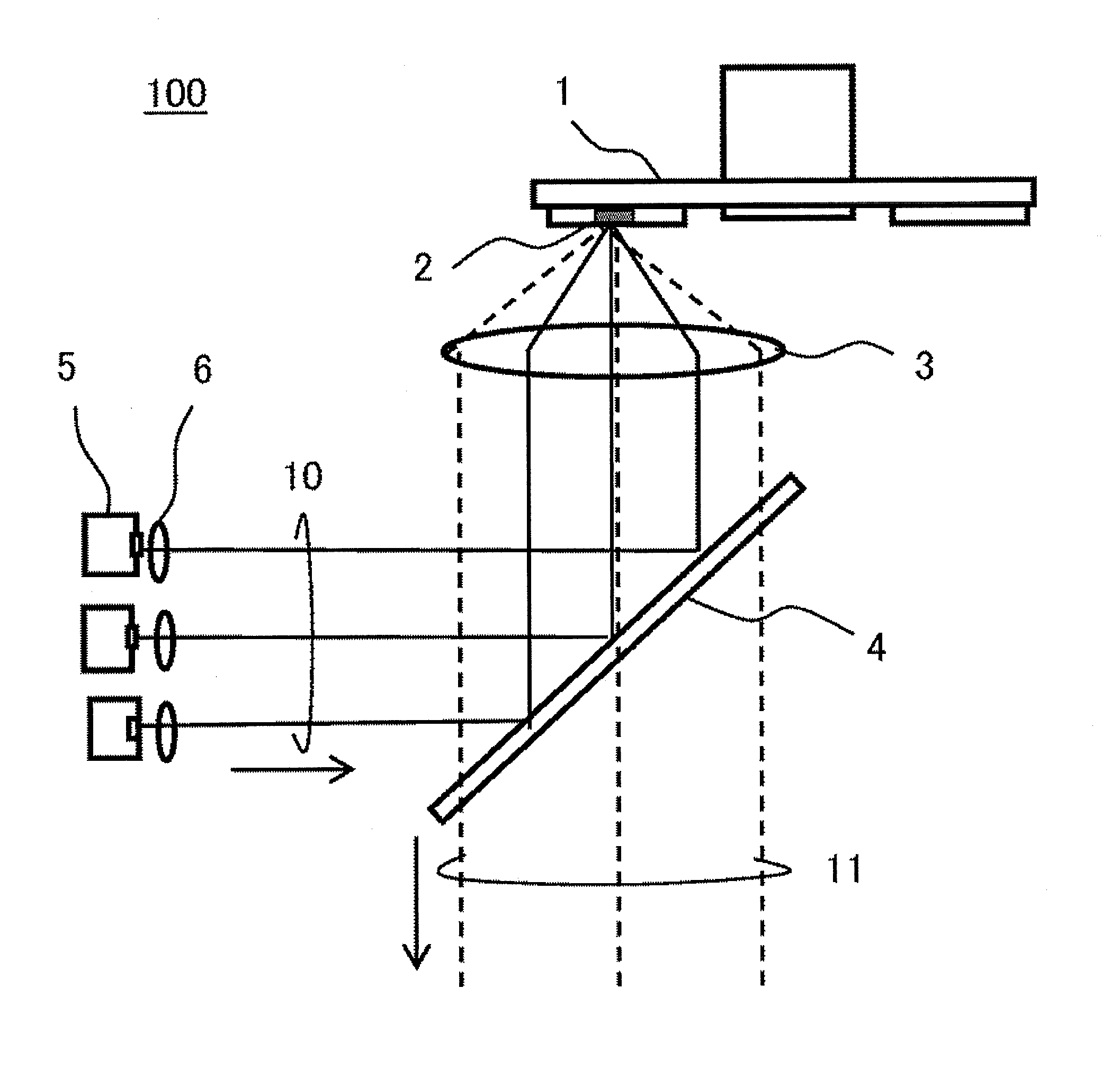
[0026]FIG. 1 is a diagram illustrating a configuration of a light source device according to a first embodiment of the present invention. A light source device 100 includes an excitation light source 5, a mirror 4, and a phosphor wheel 1 as main components. The excitation light source 5 includes one or more solid light emitting elements such as a laser light emitting element and emits a blue laser beam as excitation light, for example. Excitation light 10 (indicated by solid lines) emitted from the excitation light source 5 is made to substantially parallel by a collimate lens 6 and enters the mirror 4.
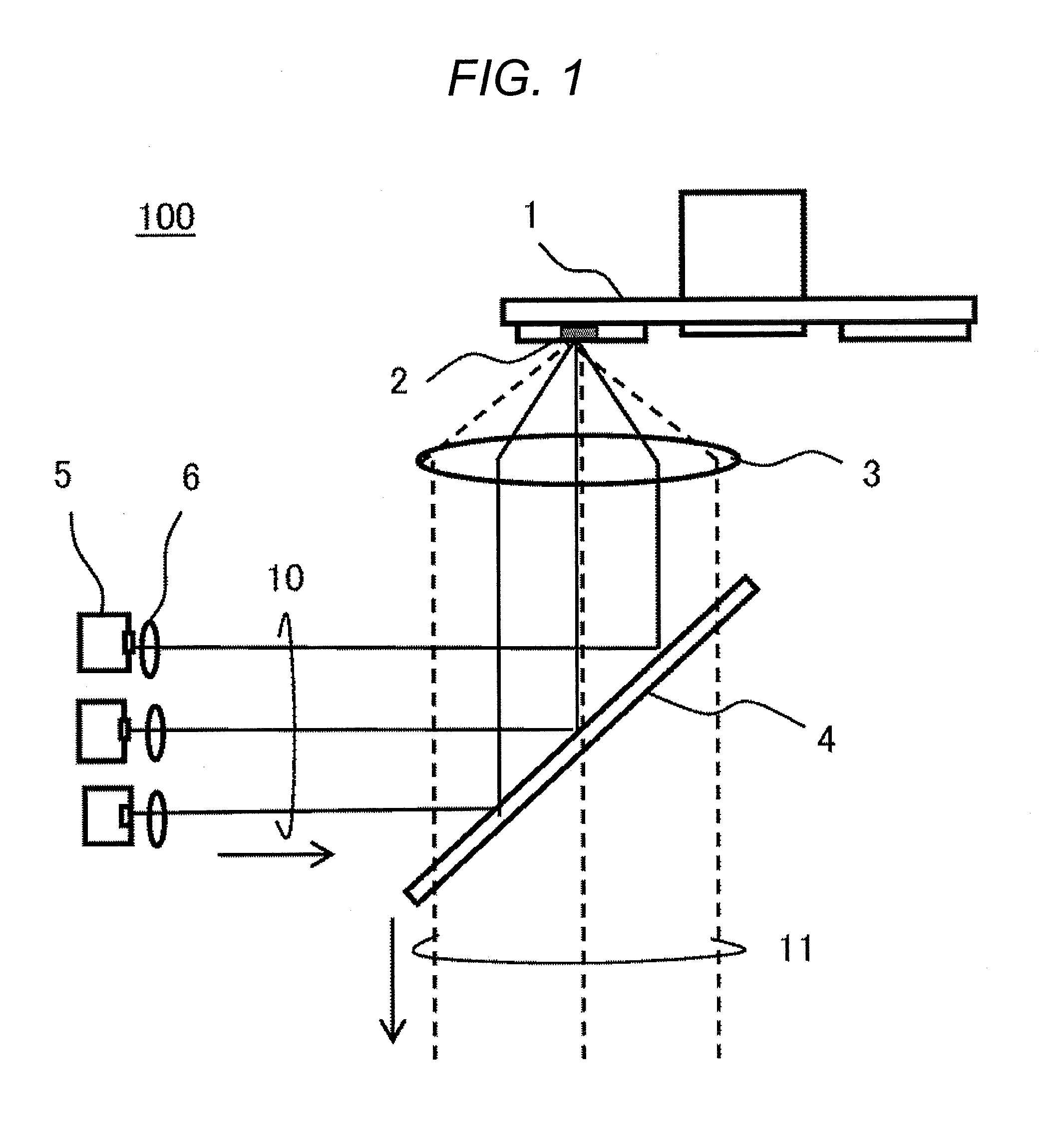
[0027]The mirror 4 includes two regions. A first region is a dichroic coated region 21 having a property to reflect a wavelength band of the excitation light (blue) and to transmit the wavelength bands of fluorescent light (red, yellow and green). A second region is a wide wavelength transmissive region 22 that transmits the wavelength bands of both the excitation light and the fluore...
second embodiment
[0042]In a second embodiment, a description will be given for a case in which a positional relation between a phosphor wheel 1 and an excitation light source 5 is changed.
[0043]FIG. 6 is a diagram illustrating a configuration of a light source device according to the second embodiment of the present invention. The basic configuration of a light source device 100′ is same as that of a first embodiment (FIG. 1); however different in following points: an excitation light source 5 is positioned at a bottom part of FIG. 6; a mirror 4′ is configured to have the inverse property in the aspects of transmission and reflection of a mirror 4; and illumination light is emitted leftward in the FIG. 6. In other words, although the mirror 4′ has a configuration illustrated in FIG. 2, a dichroic coated region 21 has the property to transmit a wavelength band of an excitation light (blue) and reflect the wavelength band of fluorescent light (red, yellow and green), and a wide wavelength reflective r...
third embodiment
[0049]A light source device according to a third embodiment is configured such that a diffused excitation light reflected by a phosphor wheel 1 may enter, avoiding a dichroic coated region of a mirror 4. With this configuration, illumination light loss caused by the dichroic coated region can be reduced. This configuration is effective in the case where the dichroic coated region cannot be formed small.
[0050]Ideally, the diffused excitation light perfectly avoids the dichroic coated region 21 and preferably all enters a wide wavelength transmissive region 22. But practically, a small amount of the diffused excitation light inevitably enters the dichroic coated region 21. Therefore, this configuration is intended to prevent the diffused excitation light from entering the dichroic coated region as much as possible.
[0051]FIG. 7 is a diagram illustrating a configuration of the light source device according to the third embodiment of the present invention. Here, a description will be giv...
PUM
 Abstract
Description
Claims
Application Information