Optical connector and method of forming plug using the optical connector

Inactive Publication Date: 2014-09-11
HIROSE ELECTRIC GROUP
View PDF9 Cites 5 Cited by
  • Summary
  • Abstract
  • Description
  • Claims
  • Application Information

AI Technical Summary

Benefits of technology

[0018]According to the present invention, the optical fiber insertion unit has a simple configuration that is composed of the ferrule and the lens sleeve, and it is not necessary to have the optical fiber in the ferrule in advance as in the conventional technique. Further, it is not necessary to perform the step of polishing an end surface of the optical fiber, so that it is possible to reduce the manufacturing cost of the optical fiber.
[0019]Furthermore, according to the present invention, the refractive index matching material applied at the front end of the ferrule enters a gap formed between the ferrule and the lens sleeve. Accordingly, it is possible to prevent the connection loss between the end of the optical fiber and the lens. Moreover, the ferrule and the lens sleeve are formed of the different materials. Accordingly, even when heat is applied on the optical fiber, and the gap between the end portion of the optical fiber and the lens is widened due to the difference in the coefficients of linear expansion of the different materials, the refractive i

Problems solved by technology

In this case, it is difficult to apply the polishing process to the optical fiber when the optical fiber is cut in the specific length at the fiber-lying site without equipment furnished in the factory.
In the conventional onsite wire-connecting method for the optical fibers, however, when the ferrule is produced, it is necessary to enclose the optical fib

Method used


Image

  • Optical connector and method of forming plug using the optical connector
  • Optical connector and method of forming plug using the optical connector
  • Optical connector and method of forming plug using the optical connector

Examples


Embodiment Construction

[0029]Hereunder, an embodiment of the present invention will be described with reference to the accompanying drawings. Here, in any of those drawings for describing embodiment of the present invention, the same reference numerals are basically used for the same members and repetitive explanation is omitted.

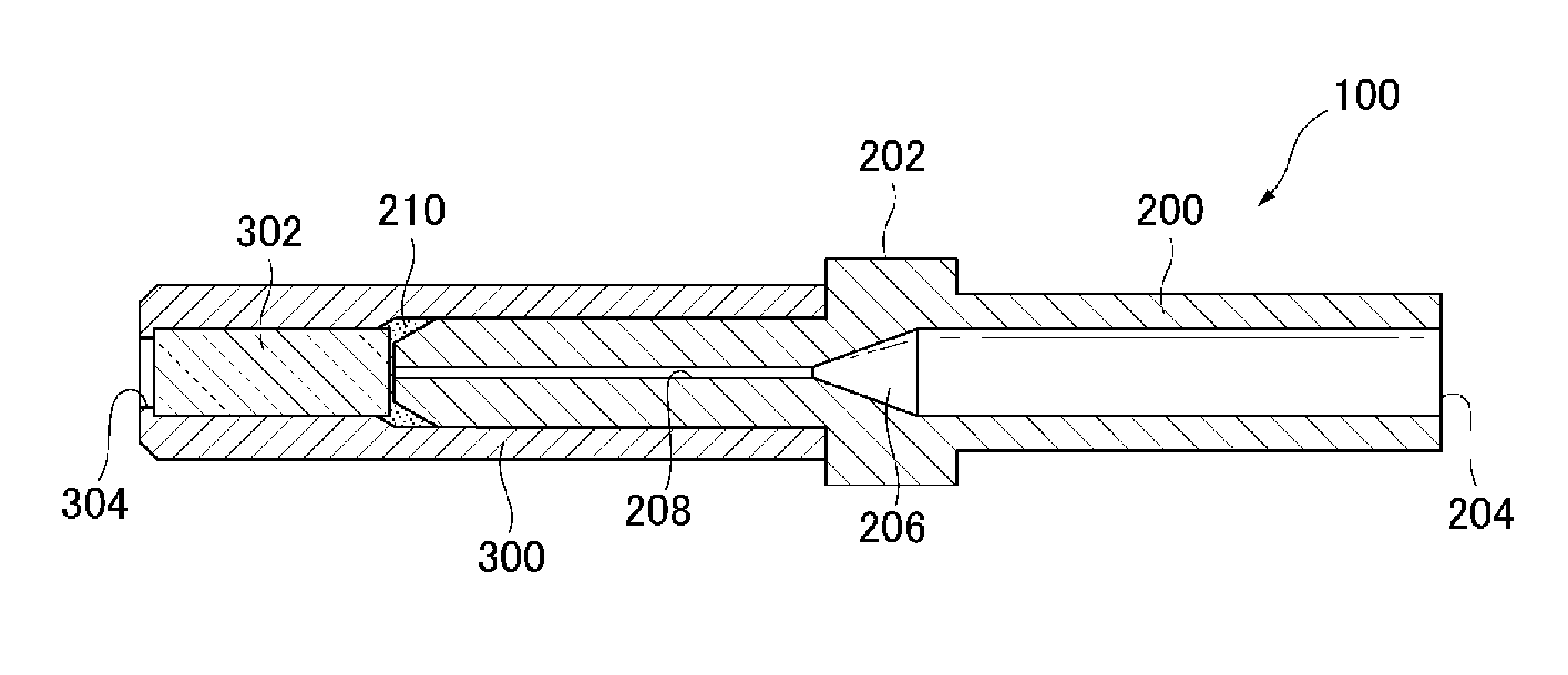
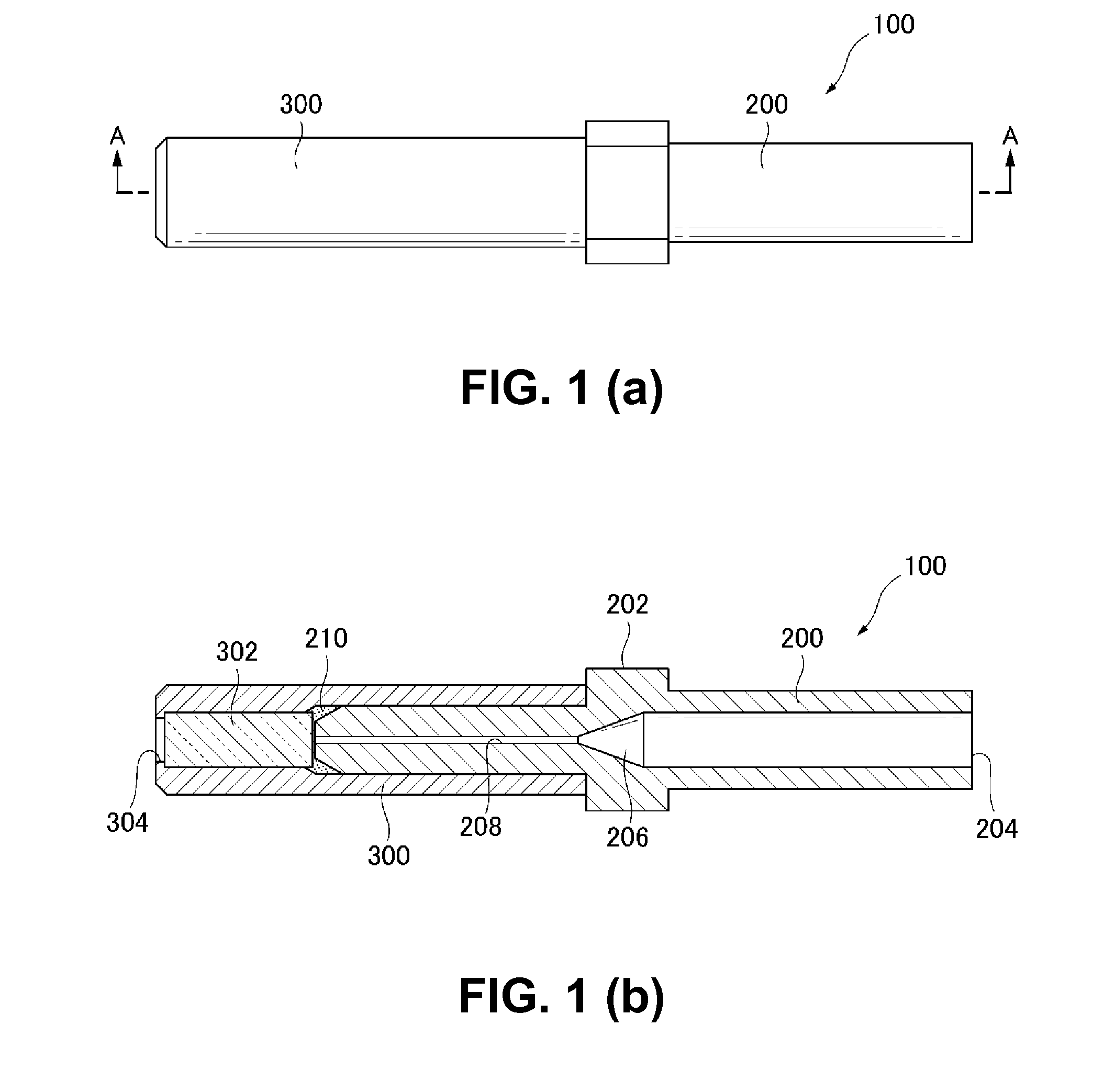
[0030]FIGS. 1(a) and 1(b) show an optical fiber insertion unit 100 according to an embodiment of the present invention. As shown in FIG. 1(a), the optical fiber insertion unit 100 is composed of a ferrule 200 and a lens sleeve 300. FIG. 1(b) is a sectional view of the optical fiber insertion unit 100 taken along the line A-A in FIG. 1(a).

[0031]As shown in FIGS. 1(a) and 1(b), the ferrule 200 has a cylindrical shape. Further, the ferrule 200 has a flange 202 in a center part on an outer side thereof, and an optical fiber insertion hole 204 in an inner side thereof for inserting an optical fiber in the ferrule 200. Further, the ferrule 200 has an optical fiber guide surface 206 havi...


PUM

PropertyMeasurementUnit
Elasticityaaaaaaaaaa
Refractive indexaaaaaaaaaa
Fluidityaaaaaaaaaa

Abstract

An optical fiber insertion unit includes a ferrule; a lens sleeve having a lens at a front end portion thereof and a ferrule insertion opening portion at a rear end portion thereof for inserting the ferrule; and a refractive index matching portion disposed between the ferrule and the lens sleeve. The refractive index matching portion is filled with a refractive index matching material so that the refractive index adjusting agent contacts with at least the lens.

Description

BACKGROUND OF THE INVENTION AND RELATED ART STATEMENT[0001]The present invention relates to an optical connector, and a method of connecting an optical fiber to the optical connector on-site such as a site of optical fiber-lying work.[0002]Generally speaking, at a factory of producing an optical fiber cable having an optical connector at an end part thereof, first, the optical fiber is cut into a standard length in advance. Afterward, in order to reduce a connection loss due to roughness of an end surface of the optical fiber, the end surface of the optical fiber is subjected to a polishing process. On the other hand, at an optical fiber-lying site, since the lengths of the optical fibers to be used may vary according to the optical fiber-lying site, each optical fiber is cut into a specific length each time, rather than using the optical fiber already cut in the standard length at the factory. In this case, it is difficult to apply the polishing process to the optical fiber when th...

Claims


Application Information

Patent Timeline
IPC IPC(8): G02B6/38
CPCG02B6/3853G02B6/3878G02B6/3891G02B6/32Y10T29/49826
Inventor HIYAMA, YOSHIYUKIMATSUMOTO, SHINICHI
Owner HIROSE ELECTRIC GROUP
Why Eureka
Try Eureka