
Retarding downshift management

a technology of retarding unit and downshift, which is applied in the direction of brake system, instruments, transportation and packaging, etc., can solve the problems of excessive wear of drivetrain components

Active Publication Date: 2014-09-11
CATERPILLAR INC
View PDF10 Cites 4 Cited by
  • Summary
  • Abstract
  • Description
  • Claims
  • Application Information

AI Technical Summary

Benefits of technology

The patent describes a method and controller for managing the use of a retarder in a vehicle. The controller uses data from sensors to automatically determine the desired level of retarding based on the vehicle's angle, gear, and other factors. This allows for smoother and more efficient use of the retarder, improving safety and efficiency on the road. The technical effects include improved safety and efficiency through smoother use of the retarder and improved performance of the vehicle.

Problems solved by technology

In this, and some other conditions, the retarder may cause a rough downshift, which at a minimum is uncomfortable for the operator and at worst, may cause undue wear on drivetrain components.

Method used


Image

  • Retarding downshift management
  • Retarding downshift management
  • Retarding downshift management

Examples


Embodiment Construction

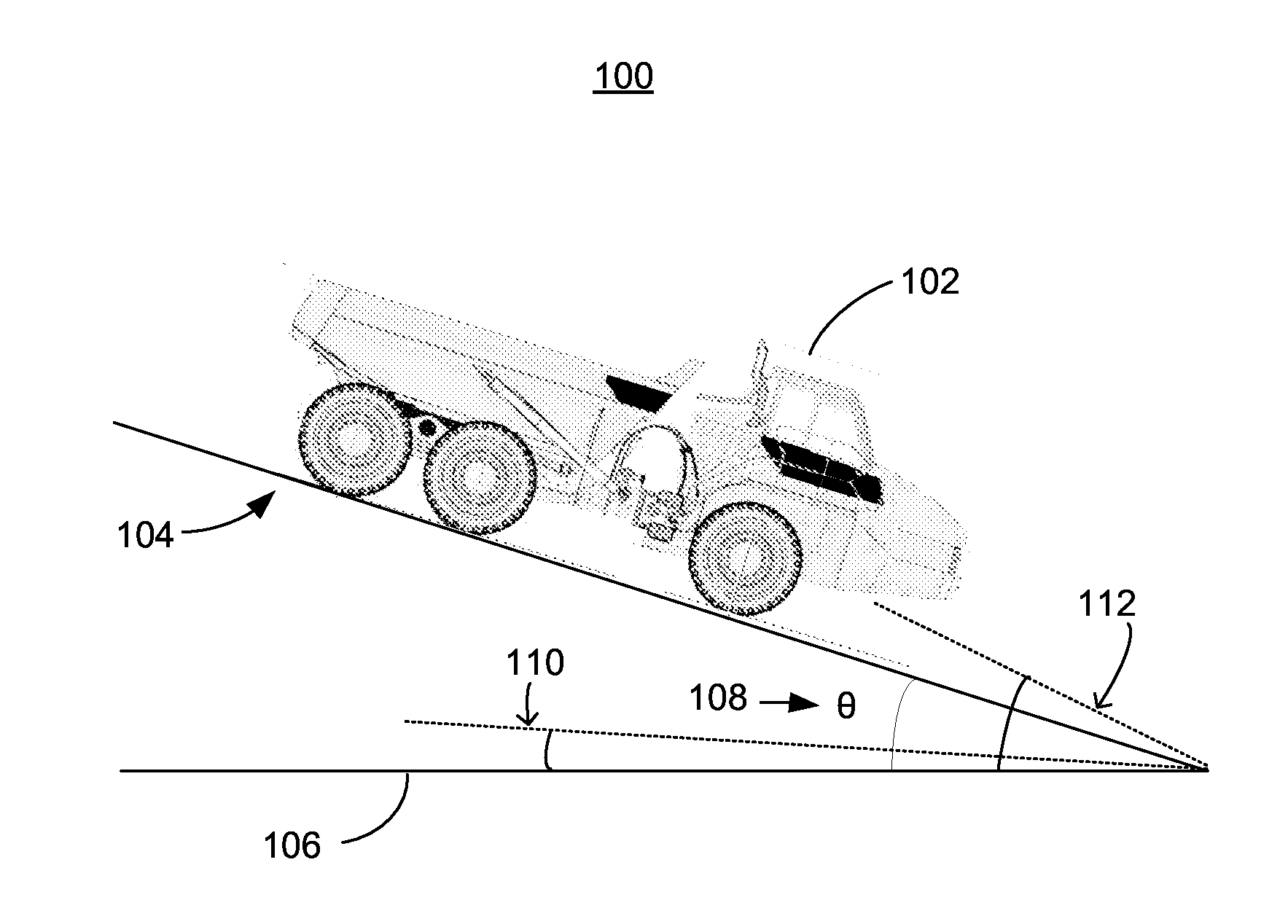
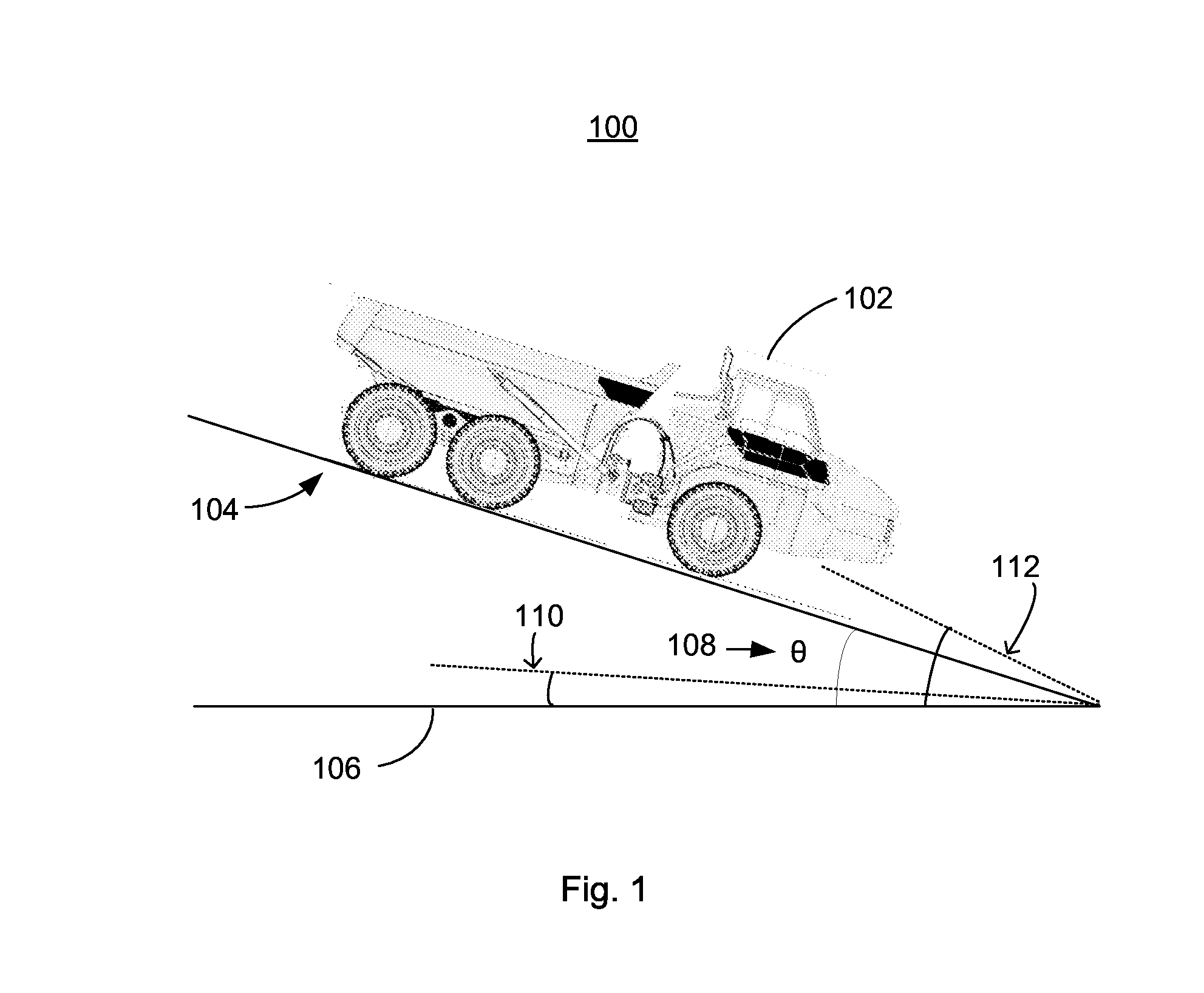
[0011]FIG. 1 illustrates a worksite 100 with a vehicle 102 positioned in a downhill attitude on an incline 104. The incline 104 may be at an angle θ108 measured from the horizontal 106. For the purpose of the following discussion, a low angle threshold 110 and a high angle threshold 112 are also depicted in FIG. 1.

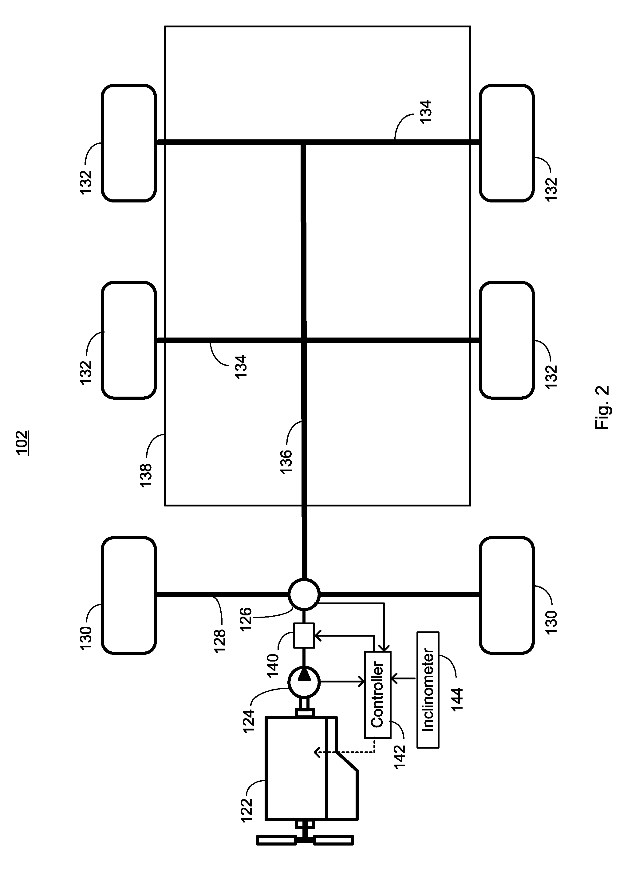
[0012]FIG. 2 is a highly simplified block diagram of the vehicle 102 illustrated in FIG. 1. In this exemplary embodiment, the vehicle 102 is shown as having an engine 122, a torque converter 124, and a transmission 126 that drives an axle 128 and front drive wheels 130. Additional drive wheels 132 may be connected by axles 134 and driven via a driveshaft 136. In practice, the drivetrain may be significantly more complex and may include inter-axle differentials and cross-axle differentials to improve traction, which are beyond the scope of the current disclosure. In an embodiment, a payload may be carried in a payload box 138. Other vehicle or machine types may have differe...


PUM


Abstract

A retarding unit in a vehicle is automatically controlled based on conditions including a current setting of the retarding control, downhill grade, speed, current gear, and impending gear change. With the retarder control set in the high position, when the vehicle is operating at a downhill angle greater than the low angle threshold and less than the high angle threshold, and the pending gear is a large step downshift, automatically setting a retarder level to a low retarder level. When the vehicle is operating on level ground and the pending gear is a large step downshift or the current gear is first or second gear, automatically setting the retarder level to off. When the vehicle is operating on flat ground and the deceleration is above a trigger level, automatically setting the retarder level to a low retarder level.

Description

TECHNICAL FIELD[0001]The present disclosure relates to a propulsion system for a large vehicle and more particularly to management of a retarding unit during vehicle operation.BACKGROUND[0002]Heavy equipment, such as large earthmoving vehicles, can use a retarder to supplement the braking provided by conventional brakes. Retarder operation is based on a manual setting and is either on or off. Some types of retarder have various level settings. When on, the retarder is active in all driving conditions including slowing to a stop by downshifting through low gears. In this, and some other conditions, the retarder may cause a rough downshift, which at a minimum is uncomfortable for the operator and at worst, may cause undue wear on drivetrain components.[0003]U.S. Patent Publication No. 20110125376 (“the '376 publication”) describes an automatic downhill speed control system in a machine. The published application describes a retarder control for slowing the machine. The retarder can be...

Claims


Application Information

Patent Timeline
Patent Type & Authority Applications(United States)
IPC IPC(8): F16H61/21
CPCF16H61/21B60T7/12B60T10/00B60T2210/20B60T2201/04B60T1/087
Inventor SCHWARTZ, TIMOTHY D.LANDES, JAMES
Owner CATERPILLAR INC
Learn More