Methods for the repair of gas turbine engine components using additive manufacturing techniques

a gas turbine engine and additive manufacturing technology, applied in the field of gas turbine engines, can solve the problems of not being able or desired to subject the entire component to these operations during repair, not being able to fit the entire component, and being in the working range of am equipment, etc., to achieve rapid prototyping or additive layer manufacturing, reduce the need for complex fixation, and be easy to join

Active Publication Date: 2014-09-18
HONEYWELL INT INC
View PDF4 Cites 33 Cited by
  • Summary
  • Abstract
  • Description
  • Claims
  • Application Information

AI Technical Summary

Benefits of technology

[0028]In some embodiments, the design phase step 210 may be performed so as to include one or more “locking” features into the design of the replacement portion. As used herein, the term locking feature refers to a design feature on the replacement portion that is added to allow the replacement portion to be more easily joined with the damaged component. It is also useful in reducing the necessity for complex fixturing to hold the damaged component in place during the joining operation. In one embodiment, a locking feature may include flanges disposed along peripheral edges of the replacement portion. Such peripheral flanges may enable the replacement portion to be more easily secured into the damaged component, and further may enable the replacement portion to remain immobile during the brazing or welding operations that may be employed to secure the replacement portion in place. Such peripheral flanges would align with corresponding peripheral flanges 502 machined onto the exterior surface of the damaged component 501 immediately adjacent to the machined-out portion. In another embodiment, as shown in FIG. 5, a locking feature may include protrusions and recesses 503 along the edges of the replacement portion 504. These protrusions and recesses will be fitted into protrusions and recesses 502 that are machined onto the edges of the damaged component 501. The two components can be then fit together either by press-fitting, sliding fit (lateral or perpendicular insertation), or any other similar mechanism that enables holding both components together during the joining operation. The pattern, size, and shape of such a locking mechanism can be variable depending on part size, shape, material, joining process, and other manufacturing and product parameters. In another embodiment, shown in FIG. 6, the locking features (602, 603) are made utilizing a joining material 604, such as braze metal or specific weld metal, to make such features onto the end of the replacement piece 605 by AMM means. The joining material can be different from the bulk material of the damaged component 601 and replacement piece 605. The replacement piece 605 can thus be manufactured in bulk (having the same shape and size), with the joining material 604, made using the methods described herein, serving as the link between the two. This will serve the purpose of precisely locating the joining material where it best serves purpose for design requirements and also easing manufacturing issues with filler material placement.
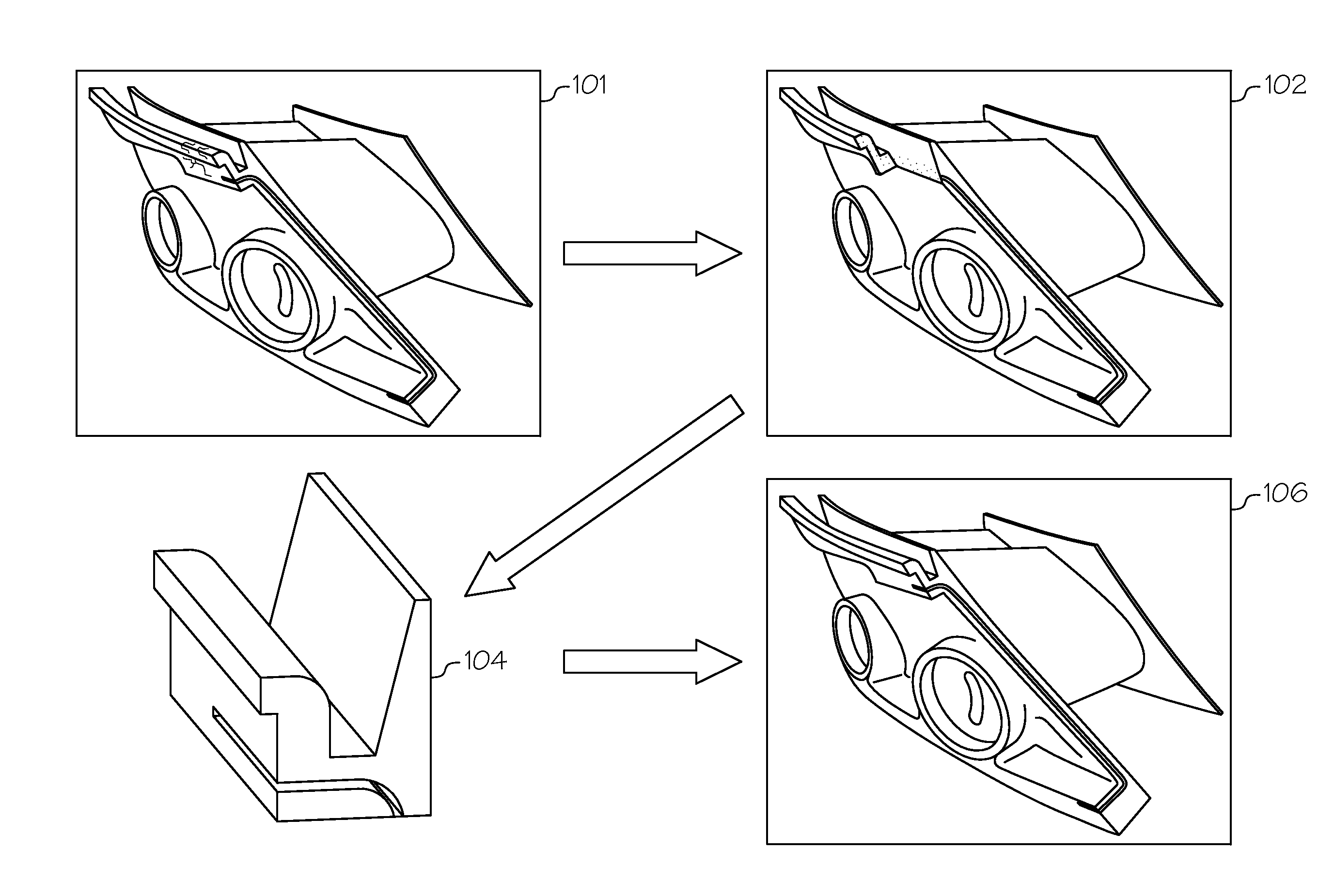
[0029]In step 220 of the method 200, the replacement portion of the gas turbine engine component is formed according to the model of step 210. In one exemplary embodiment, the replacement portion of the gas turbine engine component is formed using a rapid prototyping or additive layer manufacturing process. Some examples of additive layer manufacturing processes include: micro-pen deposition in which liquid media is dispensed with precision at the pen tip and then cured; selective laser sintering in which a laser is used to sinter a powder media in precisely controlled locations; laser wire deposition in which a wire feedstock is melted by a laser and then deposited and solidified in precise locations to build the product; electron beam melting; laser engineered net shaping; and direct metal deposition. In general, additive manufacturing techniques provide flexibility in free-form fabrication without geometric constraints, fast material processing time, and innovative joining techniques. In one particular exemplary embodiment, direct metal laser fusion (DMLF) is used to produce the replacement portion of the gas turbine engine component in step 220. DMLF is a commercially available laser-based rapid prototyping and tooling process by which complex parts may be directly produced by precision melting and solidification of metal powder into successive layers of larger structures, each layer corresponding to a cross-sectional layer of the 3D component.

Problems solved by technology

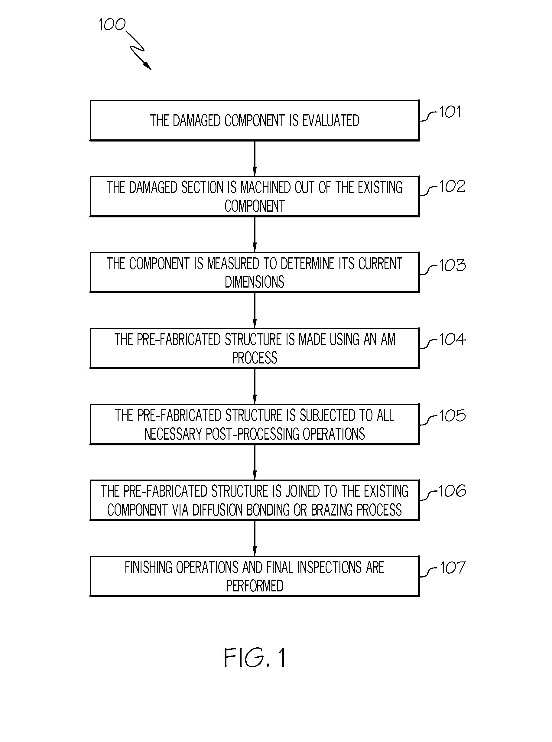
In many cases, however, it is not possible to fit the entire component (which may have been originally cast or fabricated through non-AM means) into the working range of the AM equipment.
Also, considering that certain materials made with AM require special post-processing operations such as hot isostatic pressing (HIP) and coating, it may not be possible or desired to subject the entire component to these operations during repair.

Method used


Image

  • Methods for the repair of gas turbine engine components using additive manufacturing techniques
  • Methods for the repair of gas turbine engine components using additive manufacturing techniques
  • Methods for the repair of gas turbine engine components using additive manufacturing techniques

Examples


Embodiment Construction

[0016]The following detailed description is merely exemplary in nature and is not intended to limit the invention or the application and uses of the invention. As used herein, the word “exemplary” means “serving as an example, instance, or illustration.” Thus, any embodiment described herein as “exemplary” is not necessarily to be construed as preferred or advantageous over other embodiments. Furthermore, as used herein, numerical ordinals such as “first,”“second,”“third,” etc., such as first, second, and third components, simply denote different singles of a plurality unless specifically defined by language in the appended claims. All of the embodiments and implementations of the gas turbine engine components and methods for the manufacture thereof described herein are exemplary embodiments provided to enable persons skilled in the art to make or use the invention and not to limit the scope of the invention, which is defined by the claims. Furthermore, there is no intention to be b...


PUM

PropertyMeasurementUnit
poweraaaaaaaaaa
pressureaaaaaaaaaa
temperatureaaaaaaaaaa

Abstract

In accordance with an exemplary embodiment, a method for repairing a damaged metallic component using additive manufacturing techniques includes separating a damaged portion of the damaged metallic component from an undamaged portion of the damaged metallic component, measuring the undamaged portion to determine the dimensions of the removed damaged portion, fabricating a replacement portion using additive manufacturing techniques in accordance with the determined dimensions of the removed damaged portion, and joining the replacement portion with the undamaged portion of the damaged metallic component to form a repaired metallic component.

Description

TECHNICAL FIELD[0001]An embodiment of the present disclosure generally relates to gas turbine engines, and more particularly relates to improved methods of repairing components for use in gas turbine engines.BACKGROUND[0002]A gas turbine engine may be used to power aircraft or various other types of vehicles and systems. The engine typically includes a compressor that receives and compresses an incoming gas such as air; a combustion chamber in which the compressed gas is mixed with fuel and burned to produce exhaust gas; and one or more turbines that extract energy from the high-pressure, high-velocity exhaust gas exiting the combustion chamber.[0003]Recently, additive manufacturing (AM) methods have emerged, including for example the use of direct metal laser sintering / fusion (DMLS) / (DMLF), selective laser sintering (SLS), and electron beam melting (EBM), to eliminate the need for tooling, which is expected to result in significant cost and cycle time reduction in the manufacture o...

Claims


Application Information

Patent Timeline
Patent Type & Authority Applications(United States)
IPC IPC(8): B23P6/00
CPCB23P6/002B22F7/062B23P6/005F01D5/005B22F5/04B22F2007/068B23K1/0018Y10T29/49318Y10T29/4973B23K2101/001Y02P10/25B22F10/62B22F10/66B22F10/25B22F10/64B22F10/28
Inventor BAUGHMAN, BRIAN G.WINCHESTER, GARYHEHMANN, WILLIAM F.GODFREY, DONALD G.
Owner HONEYWELL INT INC
Why Eureka
Try Eureka