Eureka AIR delivers breakthrough ideas for toughest innovation challenges, trusted by R&D personnel around the world.

Micromixing cap assembly

Active Publication Date: 2014-09-18
GENERAL ELECTRIC CO
View PDF6 Cites 20 Cited by
  • Summary
  • Abstract
  • Description
  • Claims
  • Application Information

AI Technical Summary

Benefits of technology

The patent describes different embodiments of a combustor cap assembly for a multi-tube fuel nozzle. These embodiments all include a support structure, a plurality of mixing tubes, an air distributor, and a combustor cap. The method for assembling these components is also described. The technical effects of the invention include improved fuel mixing and distribution, increased efficiency of air utilization, and reduced emissions.

Problems solved by technology

The design and construction of the fuel nozzle assembly can significantly affect the mixing and combustion of fuel and air, which in turn can impact exhaust emissions (e.g., nitrogen oxides, carbon monoxide, etc.) and power output of the gas turbine engine.
Furthermore, the design and construction of the fuel nozzle assembly can significantly affect the time, cost, and complexity of installation, removal, maintenance, and general servicing.

Method used


Image

  • Micromixing cap assembly
  • Micromixing cap assembly
  • Micromixing cap assembly

Examples


Embodiment Construction

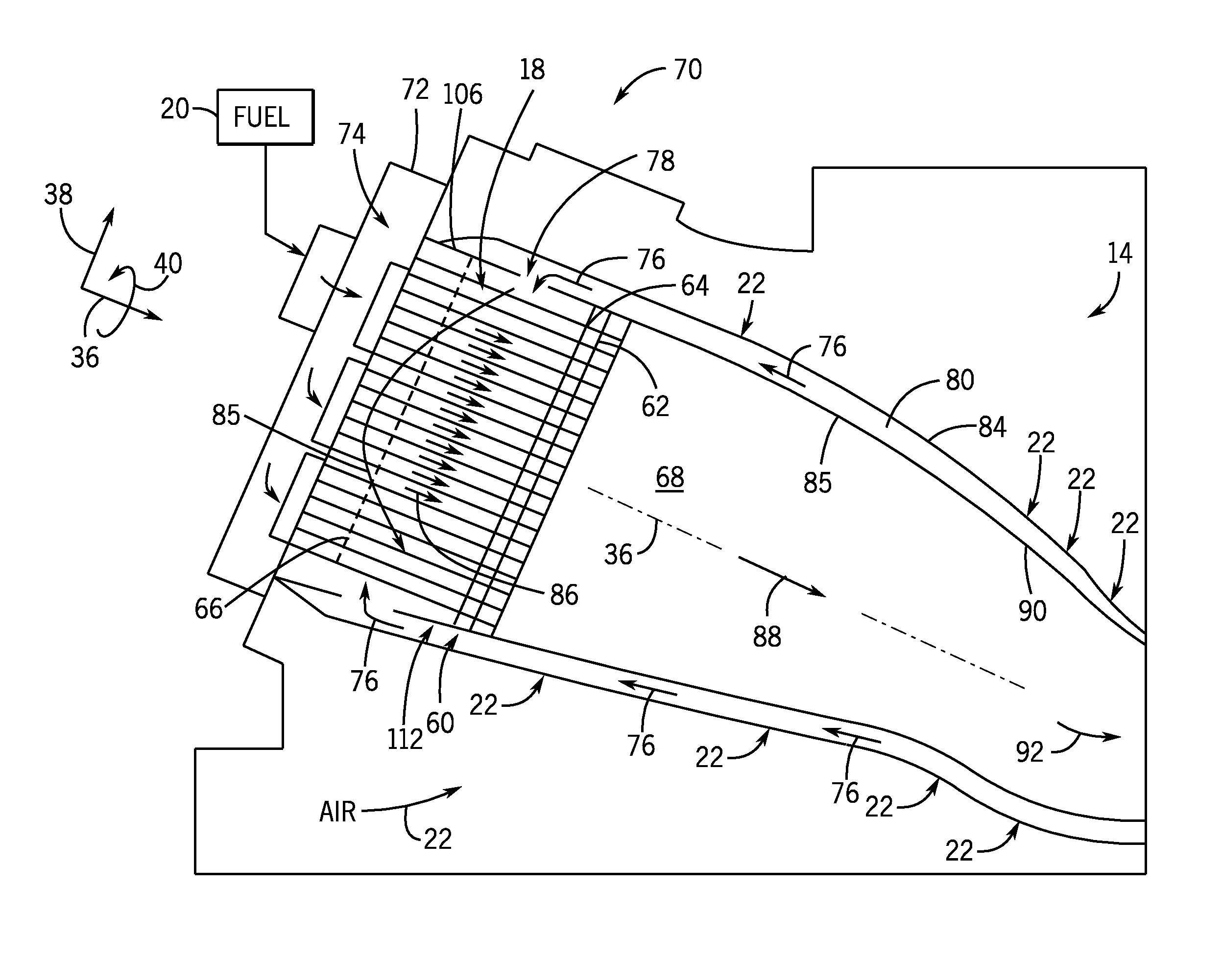
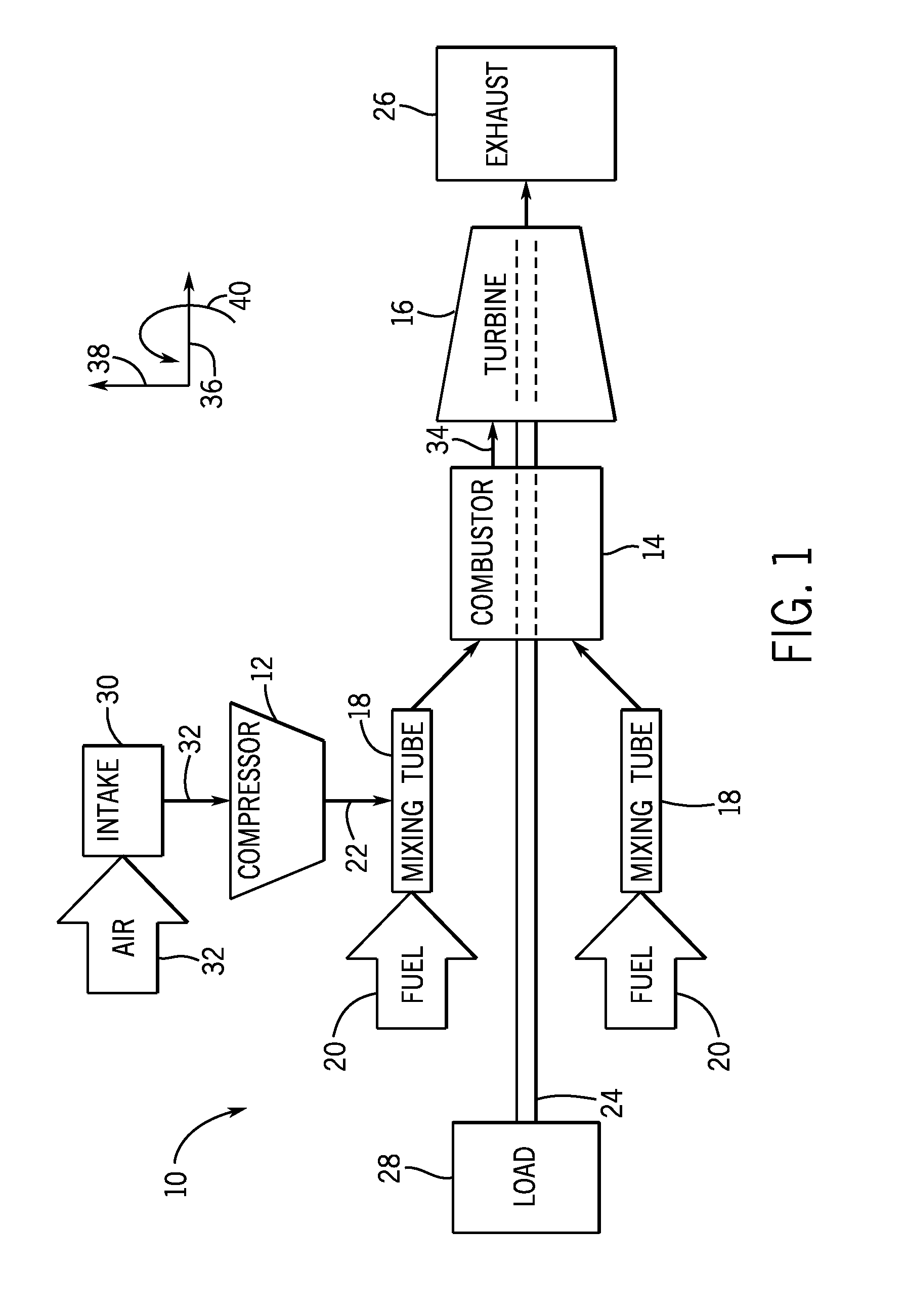
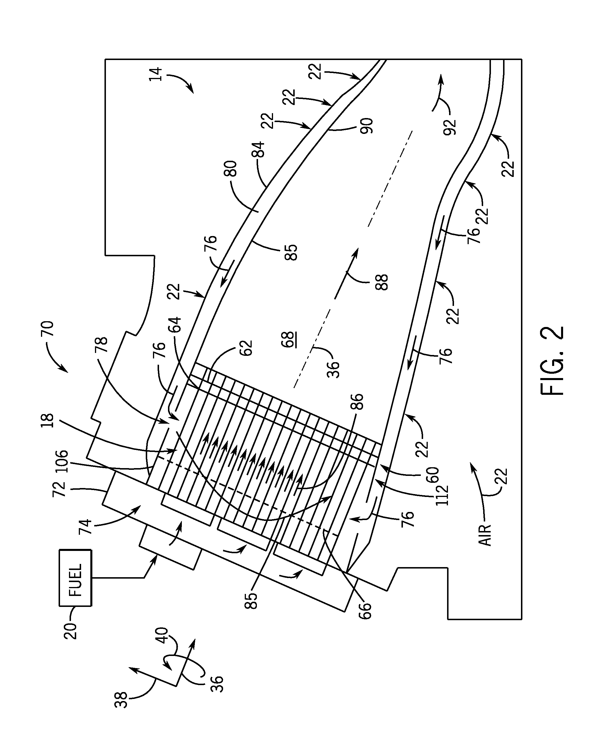
[0014]This written description uses examples to disclose the invention, including the best mode, and also to enable any person skilled in the art to practice the invention, including making and using any devices or systems and performing any incorporated methods. The patentable scope of the invention is defined by the claims, and may include other examples that occur to those skilled in the art. Such other examples are intended to be within the scope of the claims if they have structural elements that do not differ from the literal language of the claims, or if they include equivalent structural elements with insubstantial differences from the literal languages of the claims.

[0015]When introducing elements of various embodiments of the present invention, the articles “a,”“an,”“the,” and “said” are intended to mean that there are one or more of the elements. The terms “comprising,”“including,” and “having” are intended to be inclusive and mean that there may be additional elements ot...


PUM


Abstract

A system includes a combustor cap assembly for a multi-tube fuel nozzle. The combustor cap assembly includes a support structure defining an interior volume configured to receive an air flow, a plurality of mixing tubes disposed within the interior volume, wherein each of the plurality of mixing tubes comprises a respective fuel injector and is individually removable from the combustor cap assembly, an air distributor disposed within the interior volume and configured to distribute the air flow received by the interior volume to each of the plurality of mixing tubes, and a combustor cap removably coupled to the support structure.

Description

BACKGROUND[0001]The subject matter disclosed herein relates generally to turbine combustors, and, more particularly to a cap for the turbine combustors.[0002]A gas turbine engine combusts a mixture of fuel and air to generate hot combustion gases, which in turn drive one or more turbine stages. In particular, the hot combustion gases force turbine blades to rotate, thereby driving a shaft to rotate one or more loads, e.g., an electrical generator. The gas turbine engine includes a fuel nozzle assembly, e.g., with multiple fuel nozzles, to inject fuel and air into a combustor. The design and construction of the fuel nozzle assembly can significantly affect the mixing and combustion of fuel and air, which in turn can impact exhaust emissions (e.g., nitrogen oxides, carbon monoxide, etc.) and power output of the gas turbine engine. Furthermore, the design and construction of the fuel nozzle assembly can significantly affect the time, cost, and complexity of installation, removal, maint...

Claims


Application Information

Patent Timeline
IPC IPC(8): F23R3/28
CPCF23R3/286F23R3/10Y02T50/60
Inventor WESTMORELAND, JAMES HAROLDBOARDMAN, GREGORY ALLENMELTON, PATRICK BENEDICT
Owner GENERAL ELECTRIC CO
Why Eureka
Eureka Blog
Learn More