
High Pressure Soft Lithography for Micro-Topographical Patterning of Molded Polymers and Composites

a technology of molded polymers and composites, applied in the directions of packaging, labelling, transportation and packaging, etc., can solve the problems of introducing contamination into the material, not providing the desired degree of surface roughness control,

Active Publication Date: 2014-09-18
NAT INST AEROSPACE ASSOC +1
View PDF15 Cites 7 Cited by
  • Summary
  • Abstract
  • Description
  • Claims
  • Application Information

AI Technical Summary

Benefits of technology

The present invention provides methods for creating surfaces with micro-structures in composite materials. These methods involve using a flexible template with surface features that are inverses of the micro-structures to be formed in the surface of an object. The flexible template is placed in a mold tool and conformed to the surface of the mold. A composite material is then applied to the flexible template and solidified to form the object. The object is then disengaged from the flexible template to reveal the surface with the micro-structures. The methods can create surfaces with improved properties such as increased surface area, reduced surface roughness, and improved adhesion.

Problems solved by technology

However, such techniques may not provide the desired degree of control of the surface roughness, and may introduce contamination into the material that can be difficult to remove.
Furthermore, if a composite material is blasted or sanded, removal of the matrix resin from the surface may expose the reinforcing fibers, which creates a point of ingress for degenerative environmental components such as water and oxygen.

Method used


Image

  • High Pressure Soft Lithography for Micro-Topographical Patterning of Molded Polymers and Composites
  • High Pressure Soft Lithography for Micro-Topographical Patterning of Molded Polymers and Composites
  • High Pressure Soft Lithography for Micro-Topographical Patterning of Molded Polymers and Composites

Examples


Embodiment Construction

[0021]For purposes of description herein, the terms “upper,”“lower,”“right,”“left,”“rear,”“front,”“vertical,”“horizontal,” and derivatives thereof shall relate to the invention as oriented in FIG. 1. However, it is to be understood that the invention may assume various alternative orientations and step sequences, except where expressly specified to the contrary. It is also to be understood that the specific devices and processes illustrated in the attached drawings, and described in the following specification, are simply exemplary embodiments of the inventive concepts defined in the appended claims. Hence, specific dimensions and other physical characteristics relating to the embodiments disclosed herein are not to be considered as limiting, unless the claims expressly state otherwise.

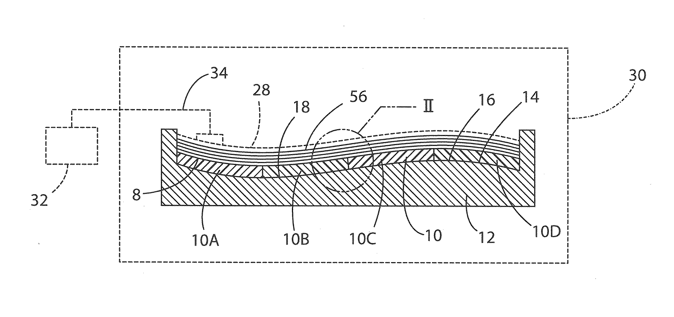
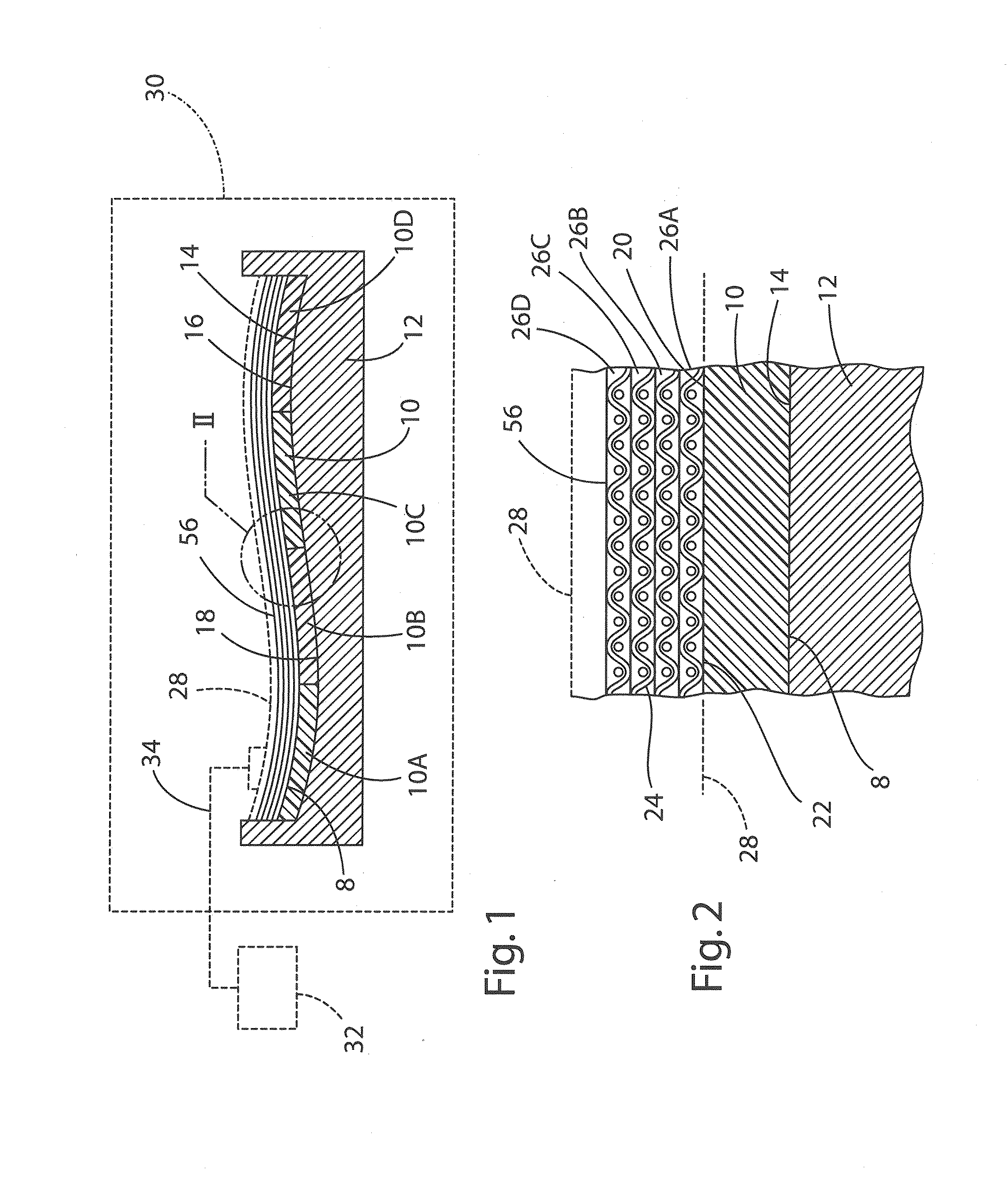
[0022]With reference to FIGS. 1 and 2, the present invention involves forming a flexible template 10 that may be positioned on or in a mold tool 12 having a mold surface 14. The mold surface 14 may in...


PUM

PropertyMeasurementUnit
Lengthaaaaaaaaaa
Lengthaaaaaaaaaa
Nanoscale particle sizeaaaaaaaaaa

Abstract

A soft lithography template or stamp is made by casting a polydimethysiloxane (PDMS) or other suitable elastomeric precursor onto a master pattern. The master pattern may be formed utilizing known micro-fabrication techniques. The PDMS template includes an inverse copy of the micro-structures on the master pattern, and can be placed into a mold used to prepare a carbon-fiber reinforced polymer composite part or other polymer molding systems where a matrix material passes through a fluid state during the cure process. The liquid resin material flows into the structures on the surface of the PDMS template and hardens during the curing cycle. After the part is released from the mold, the PDMS template can be peeled from the surface of the part to reveal the free standing micro structures which are a replica of the master pattern.

Description

CROSS-REFERENCE TO RELATED PATENT APPLICATION(S)[0001]This patent application claims the benefit of and priority to U.S. Provisional Patent Application No. 61 / 777,748, filed on Mar. 12, 2013, the contents of which are hereby incorporated by reference in their entirety.STATEMENT REGARDING FEDERALLY SPONSORED RESEARCH OR DEVELOPMENT[0002]The invention described herein was made in the performance of work under a NASA contract and by employees of the United States Government and is subject to the provisions of Public Law 96-517 (35 U.S.C. §202) and may be manufactured and used by or for the Government for governmental purposes without the payment of any royalties thereon or therefore. In accordance with 35 U.S.C. §202, the contractor elected not to retain title.BACKGROUND OF THE INVENTION[0003]Known soft lithography techniques utilize a soft polymeric mold or template made from a material such as polydimethylsiloxane (PDMS). The mold is cast using a master that comprises a hard material...

Claims


Application Information

Patent Timeline
IPC IPC(8): B29C33/38
CPCB29C33/38B29C33/3857B29C33/405B29C33/424B29K2883/00B29C33/302
Inventor PALMIERI, FRANK L.CRUZ, VINCENT B.WOHL, JR., CHRISTOPHER J.
Owner NAT INST AEROSPACE ASSOC
Learn More