Membrane-integrated energy exchange assembly

a technology of energy exchange and membrane, applied in the direction of paper/cardboard containers, lighting and heating apparatus, heating types, etc., can solve the problems of reducing the performance (measured as latent effectiveness) of the energy recovery core, affecting the performance and cost of the device, and reducing the area available for heat and moisture transfer

Active Publication Date: 2014-09-18
NORTEK AIR SOLUTIONS CANADA INC
View PDF2 Cites 66 Cited by
  • Summary
  • Abstract
  • Description
  • Claims
  • Application Information

AI Technical Summary

Problems solved by technology

Notably, the design and assembly of an energy recovery assembly may affect the heat and moisture transfer between air streams, which impacts the performance and cost of the device.
For example, if the membrane does not properly adhere to the spacer, an increase in air leakage and pressure drop may occur, thereby decreasing the performance (measured as latent effectiveness) of the energy recovery core.
Conversely, if excessive adhesive is used to secure the membrane to the spacer, the area available for heat and moisture transfer may be reduced, thereby limiting or otherwise reducing the performance of the energy recovery core.
Moreover, the use of adhesives in relation to the membrane also adds additional cost and labor during assembly of the core.
Further, the use of adhesives may result in harmful volatile organic compounds (VOCs) being emitted during initial use of an energy recovery assembly.
While energy recovery assemblies formed through wrapping techniques may reduce cost and minimize membrane waste, the processes of manufacturing such assemblies are typically labor intensive and / or use specialized automated equipment.
The wrapping may also result in leaks at edges due to faulty seals.
For example, gaps typically exist between membrane layers at corners of an energy recovery assembly.
Further, at least some known wrapping techniques result in a seam being formed that extends along membrane layers.

Method used


Image

  • Membrane-integrated energy exchange assembly
  • Membrane-integrated energy exchange assembly
  • Membrane-integrated energy exchange assembly

Examples


Embodiment Construction

[0042]The foregoing summary, as well as the following detailed description of certain embodiments will be better understood when read in conjunction with the appended drawings. As used herein, an element or step recited in the singular and proceeded with the word “a” or “an” should be understood as not excluding plural of the elements or steps, unless such exclusion is explicitly stated. Further, references to “one embodiment” are not intended to be interpreted as excluding the existence of additional embodiments that also incorporate the recited features. Moreover, unless explicitly stated to the contrary, embodiments “comprising” or “having” an element or a plurality of elements having a particular property may include additional elements not having that property.

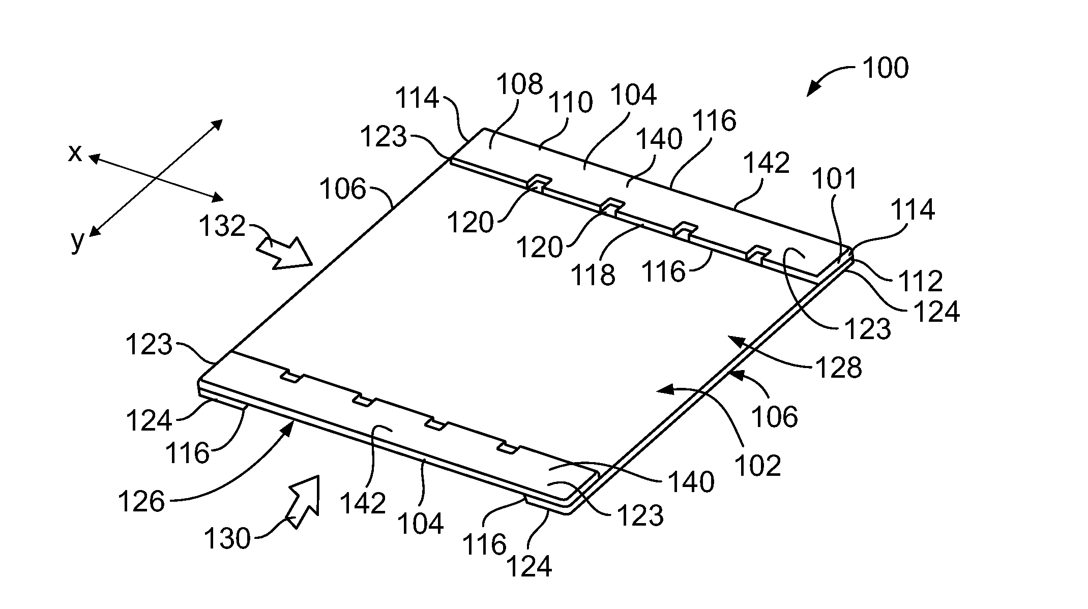
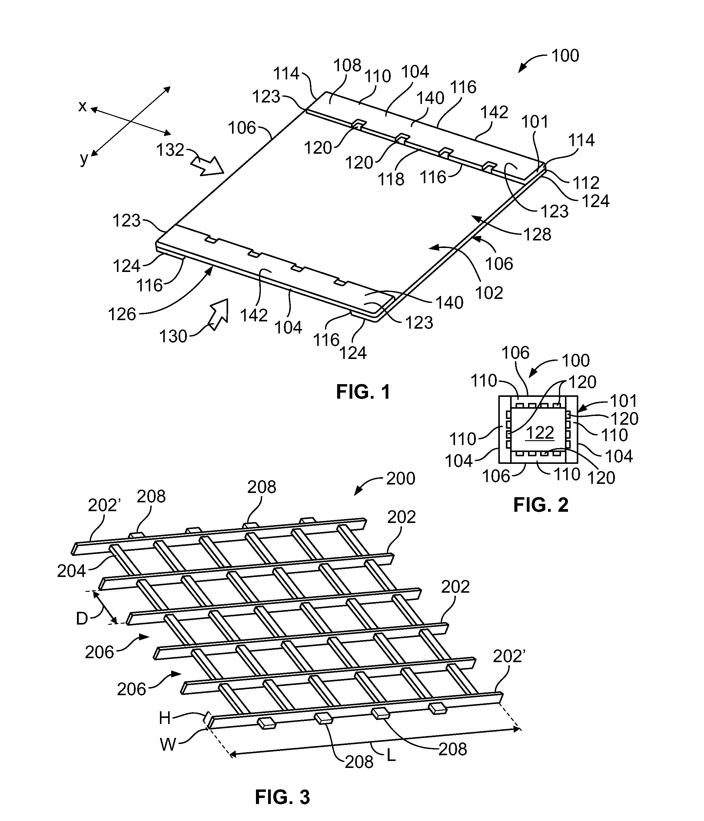
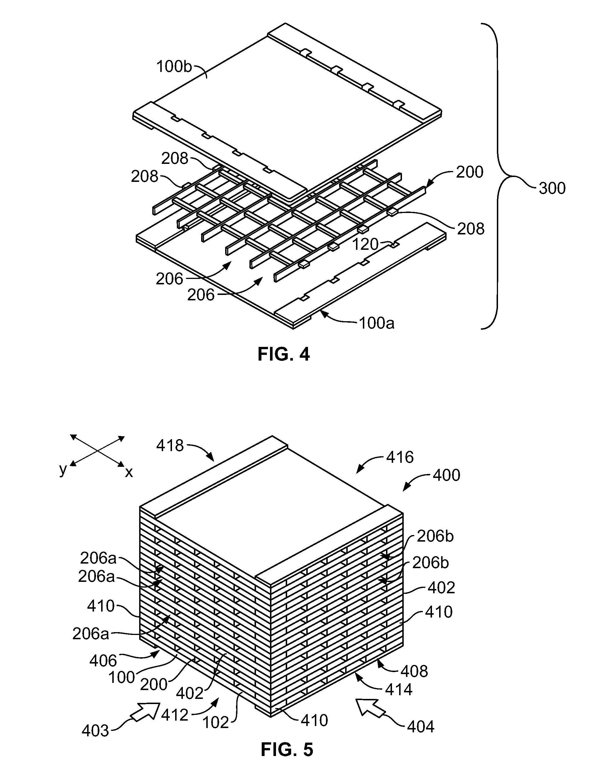
[0043]FIG. 1 illustrates a perspective top view of a membrane panel 100, according to an embodiment of the present disclosure. The membrane panel 100 may be used in an energy exchange assembly, such as an energy recovery ...


PUM

PropertyMeasurementUnit
sensible energyaaaaaaaaaa
latent energyaaaaaaaaaa
energyaaaaaaaaaa

Abstract

A method of forming a membrane panel configured to be secured within an energy exchange assembly may include forming an outer frame defining a central opening, and integrating a membrane sheet with the outer frame. The membrane sheet spans across the central opening, and is configured to transfer one or both of sensible energy or latent energy therethrough. The integrating operation may include injection-molding the outer frame to edge portions of the membrane sheet. Alternatively, the integrating operation may include laser-bonding, ultrasonically bonding, heat-sealing, or the like, the membrane sheet to the outer frame.

Description

CROSS-REFERENCE TO RELATED APPLICATIONS[0001]The present application relates to and claims priority benefits from U.S. Provisional Patent Application No. 61 / 783,048, entitled “Membrane-Integrated Energy Exchanger,” filed Mar. 14, 2013, which is hereby expressly incorporated by reference in its entirety.BACKGROUND OF THE DISCLOSURE[0002]Embodiments of the present disclosure generally relate to an energy exchange assembly, and, more particularly, to an energy exchange assembly having one or more membranes that are configured to transfer sensible and / or latent energy therethrough.[0003]Energy exchange assemblies are used to transfer energy, such as sensible and / or latent energy, between fluid streams. For example, air-to-air energy recovery cores are used in heating, ventilation, and air conditioning (HVAC) applications to transfer heat (sensible energy) and moisture (latent energy) between two airstreams. A typical energy recovery core is configured to precondition outdoor air to a de...

Claims


Application Information

Patent Timeline
Patent Type & Authority Applications(United States)
IPC IPC(8): F28D21/00
CPCF28D21/0015F28D21/0014F28D21/0008F28D9/0062F28F9/001F28F2255/143Y10T156/10
Inventor ERB, BLAKE NORMANHANSON, STEPHENAFSHIN, MOHAMMAD
Owner NORTEK AIR SOLUTIONS CANADA INC
Why Eureka
Try Eureka