Closed loop drilling fluids circulation and management system

a closed loop, fluid circulation technology, applied in the direction of chemistry apparatus and processes, borehole/well accessories, surface mining, etc., can solve the problems of high level of manual intervention, relatively expensive drilling fluid, and process challenges

Inactive Publication Date: 2014-09-18
BP CORP NORTH AMERICA INC
View PDF6 Cites 20 Cited by
  • Summary
  • Abstract
  • Description
  • Claims
  • Application Information

AI Technical Summary

Benefits of technology

[0007]These and other needs in the art are addressed in one embodiment by a closed loop drilling fluids circulation system. In an embodiment, the system comprises a first drilling fluid circulation system disposed at a first subterranean drill site. The first drilling fluid circulation system includes a supply tank for holding clean drilling fluid and a solids control device configured to separate solids from used drilling fluid. In addition, the system comprises a central processing facility disposed at a location remote from the first drill site and configured to receive used drilling fluid from the solids control device and supply clean drilling fluid to the supply tank.
[0008]These and other needs in the art are addressed in another embodiment by a drilling fluids circulation system disposed at a drill site. In an embodiment, the system comprises a pressurized storage vessel for holding clean drilling fluid at the drill site. In addition, the system comprises a supply pump configured to pump clean drilling fluid from the pressurized storage vessel down a drill string. Further, the system comprises a pressurized surge vessel configured to receive and hold used drilling fluid from an annulus disposed about the drill string. Still further, the system comprises a sealed and pressurized solids control device configured to receive used drilling fluid from the surge vessel and separate solids from used drilling fluid. Moreover, the system comprises a return pump configured to pump used drilling fluid from the solids control device.
[0009]These and other needs in the art are addressed in another embodiment by a method for circulating and processing drilling fluid. In an embodiment, the method comprises (a) receiving used drilling fluid from a borehole at a first subterranean drill site. In addition, the method comprises (b) preventing the escape of gases from the used drilling fluid at the first subterranean drill site. Further, the method comprises (c) pumping the used drilling fluid from the first subterranean drill site to a central processing facility disposed at the surface after (b). Still further, the method comprises (d) processing the used drilling fluid to form clean drilling fluid at the central processing facility. Moreover, the method comprises (e) pumping the clean drilling fluid from the central processing facility to the first subterranean drill site after (d).

Problems solved by technology

During drilling operations, the well is hydrostatically controlled with an atmospheric solids separation system, which requires a high level of manual intervention.
Drilling fluid is relatively expensive, and thus, is typically cleaned and recirculated through the drilling system.
In either case, gases exiting the drilling fluid are typically vented or flared at the drill site, and thus, can pose process challenges and contribute to greenhouse gas emissions.
Gases vented from drilling fluid can be particularly problematic when drilling in a closed and confined environment such as in a subterranean tunnel.
In addition, in environmentally sensitive areas, there may be severe restrictions on the venting and / or flaring of released gases, as well as the footprint available for drilling operations and related drilling mud circulation equipment.

Method used


Image

  • Closed loop drilling fluids circulation and management system
  • Closed loop drilling fluids circulation and management system
  • Closed loop drilling fluids circulation and management system

Examples


Embodiment Construction

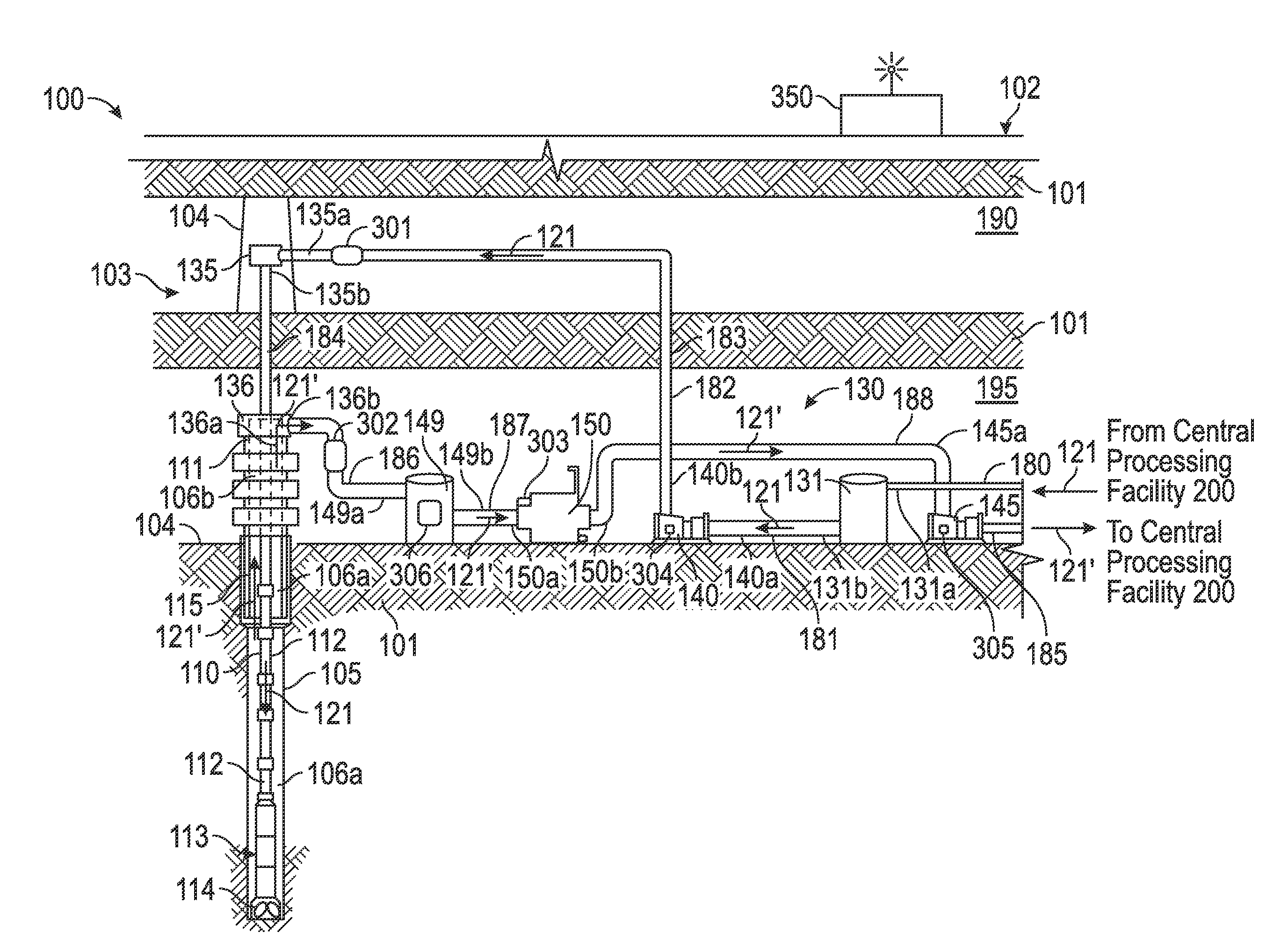
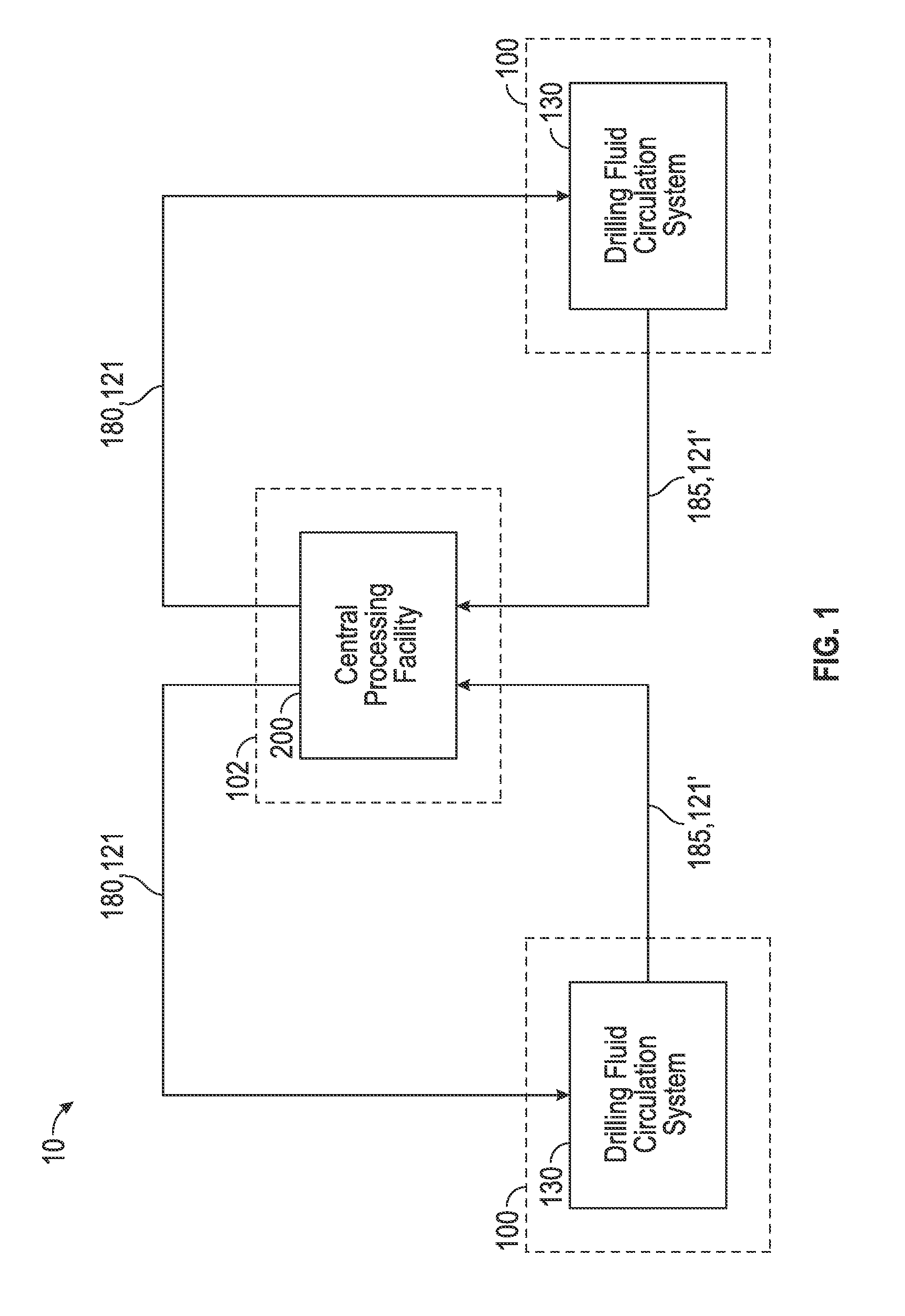
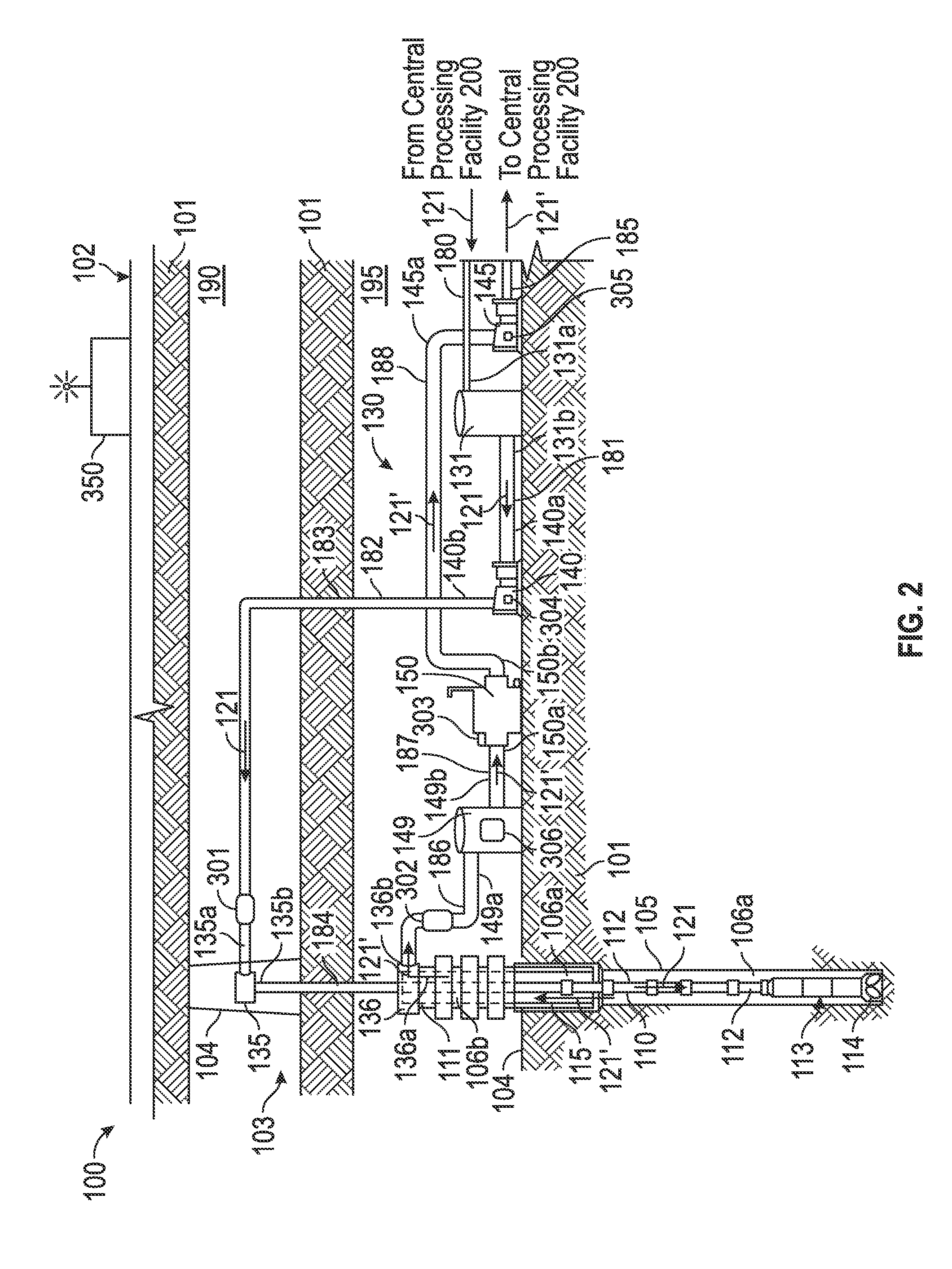
[0018]The following description is exemplary of embodiments of the disclosure. These embodiments are not to be interpreted or otherwise used as limiting the scope of the disclosure, including the claims. One skilled in the art will understand that the following description has broad application, and the discussion of any embodiment is meant only to be exemplary of that embodiment, and is not intended to suggest in any way that the scope of the disclosure, including the claims, is limited to that embodiment.

[0019]The drawing figures are not necessarily to scale. Certain features and components disclosed herein may be shown exaggerated in scale or in somewhat schematic form, and some details of conventional elements may not be shown in the interest of clarity and conciseness. In some of the figures, one or more components or aspects of a component may be not displayed or may not have reference numerals identifying the features or components that are identified elsewhere in order to im...


PUM


Abstract

A closed loop drilling fluids circulation system includes a first drilling fluid circulation system disposed at a first subterranean drill site. The first drilling fluid circulation system includes a supply tank for holding clean drilling fluid and a solids control device configured to separate solids from used drilling fluid. In addition, the system includes a central processing facility disposed at a location remote from the first drill site and configured to receive used drilling fluid from the solids control device and supply clean drilling fluid to the supply tank.

Description

CROSS-REFERENCE TO RELATED APPLICATIONS[0001]This application claims benefit of U.S. provisional patent application Ser. No. 61 / 783,979, filed Mar. 14, 2013, and entitled “Closed Loop Drilling Fluids Circulation and Management System,” which is hereby incorporated by reference in its entirety.STATEMENT REGARDING FEDERALLY SPONSORED RESEARCH OR DEVELOPMENT[0002]Not applicable.BACKGROUND[0003]Embodiments described herein relate generally to systems and methods for processing drilling mud or fluid. More particularly, embodiments described herein relate to a sealed, gas- tight closed loop systems and methods for managing and controlling the processing of drilling fluid used in subterranean drilling operations.[0004]In drilling a borehole (or wellbore) into the earth for the recovery of hydrocarbons from a subsurface formation, it is conventional practice to connect a drill bit to the lower end of a drill string, then rotate the drill bit with weight-on-bit (WOB) applied to enable the bi...

Claims


Application Information

Patent Timeline
Patent Type & Authority Applications(United States)
IPC IPC(8): E21B21/06E21B21/01E21B21/08
CPCE21B21/06E21B21/067E21B21/065E21C41/24E21B21/01E21B21/12E21B21/08E21B37/00
Inventor BEDDOES, RICHARDFOURNIER, ULRICHALL, JEFFPEATS, ALLAN
Owner BP CORP NORTH AMERICA INC
Why Eureka
Try Eureka