Eureka AIR delivers breakthrough ideas for toughest innovation challenges, trusted by R&D personnel around the world.

Ion trap device

Active Publication Date: 2014-09-18
BATTELLE MEMORIAL INST
View PDF7 Cites 4 Cited by
  • Summary
  • Abstract
  • Description
  • Claims
  • Application Information

AI Technical Summary

Benefits of technology

The present invention is about an ion trap device that can trap and manipulate ions. The device includes a series of electrodes that define an ion flow path, and a first RF field that is applied to the electrodes to create a first RF waveform on each electrode that is phase shifted approximately 180 degrees from the first RF waveform on an adjacent electrode. A DC voltage is superimposed with the RF field to create a DC gradient to drive ions in the direction of the gradient. The device also includes two or more wires that are substantially perpendicular to the ion path and repel ions. The second set of electrodes is positioned adjacent to the first set of electrodes and a DC voltage is applied to the second set of electrodes to repel ions. The spacing between the electrodes in the second set of electrodes can be equal or different from the spacing between the electrodes in the first set of electrodes. The device can include a series of stacked-ring electrodes or a combination of stacked-ring and DC-only electrodes. The angle formed by the inner diameters of the electrodes after the exit grid in the xz-plane or the yz-plane is equal to or greater than 90 degrees. The technical effects of the invention include improved ion trapping and manipulation with reduced space requirements and improved performance.

Problems solved by technology

However, these meshes do not store ions efficiently at high pressure.

Method used


Image

  • Ion trap device
  • Ion trap device
  • Ion trap device

Examples


Embodiment Construction

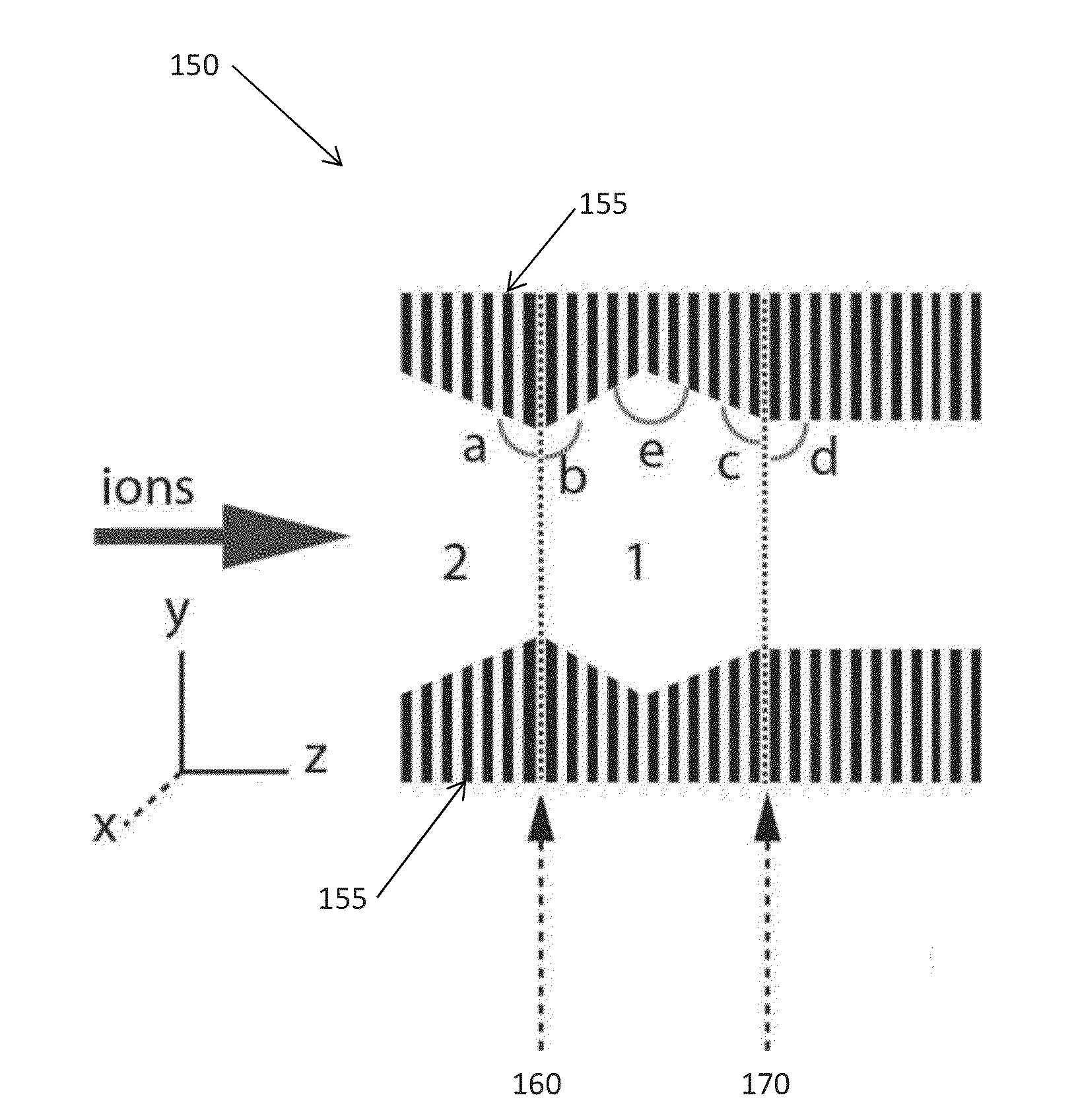
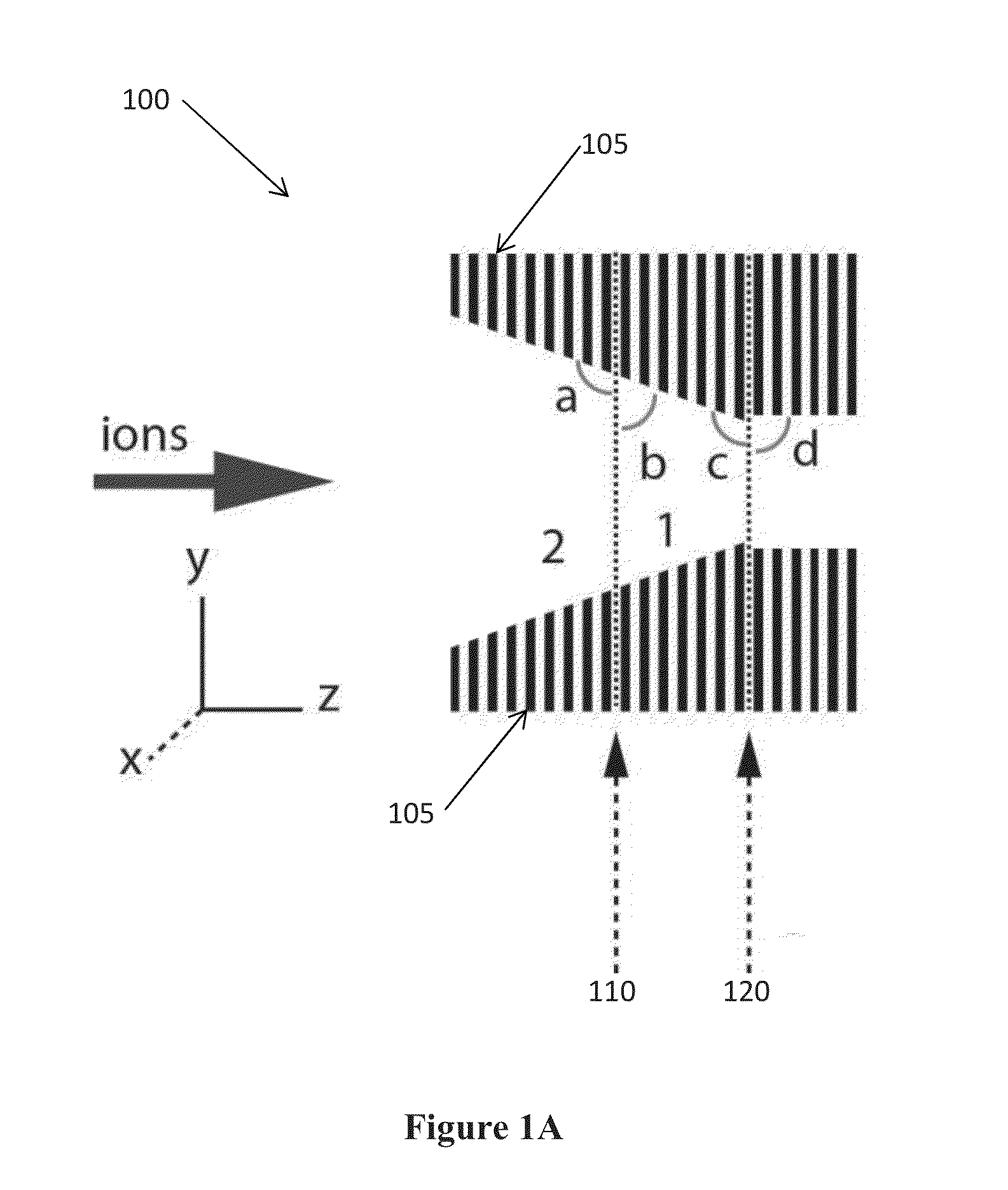
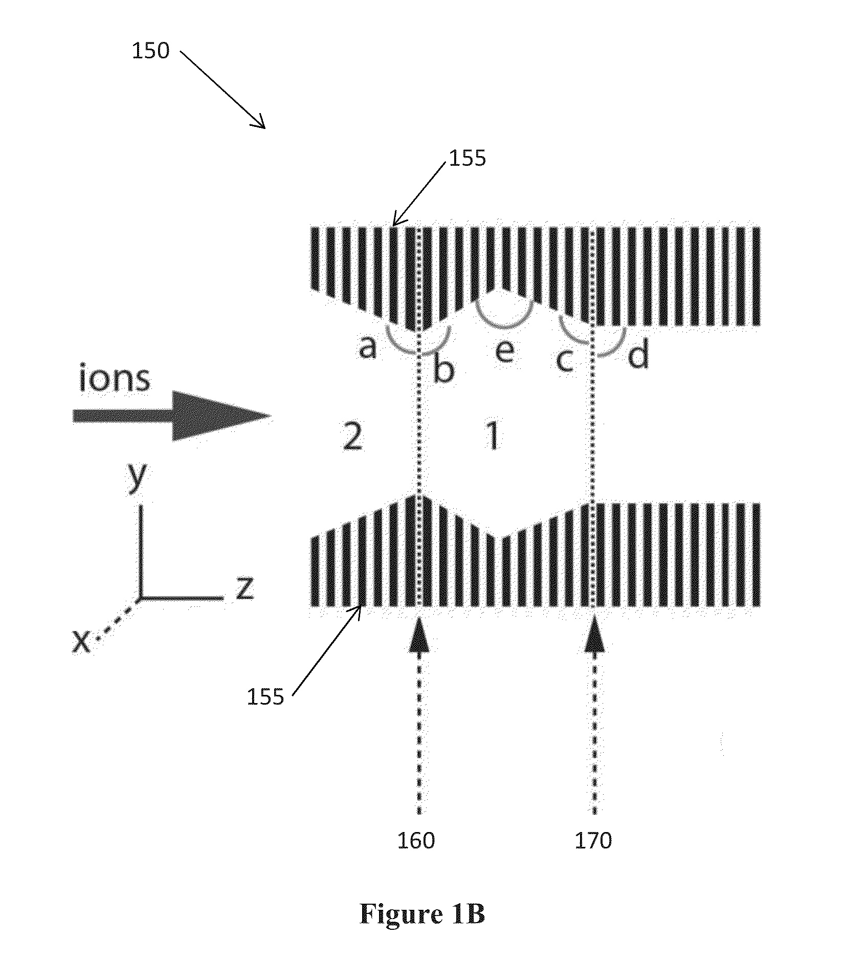
[0033]The present invention relates to methods, devices, and apparatuses for selectively trapping and releasing ions. In certain embodiments, a voltage is applied to a series or set of concentric ring electrodes—without the use of meshes—to selectively trap and release ions traveling through the rings. The voltage applied to the electrodes to repel the ions may be a RF field or a DC field. These gridless gate devices can release ions from a trap and achieve high sensitivity by reducing losses into the grids. The present invention also works efficiently at high pressures (>50 mtorr).

[0034]FIG. 1A is a schematic of an ion trap device 100, in accordance with one embodiment of the present invention. The device 100 includes a series of electrodes 105, an entrance grid 110, and an exit grid 120. Ions are transmitted through an opening of the electrodes 105 toward the middle of the device 100. The electrodes 105 may be ring electrodes, and the ring electrodes may be assembled in stacks.

[00...


PUM


Abstract

An ion trap device is disclosed. The device includes a series of electrodes that define an ion flow path. A radio frequency (RF) field is applied to the series of electrodes such that each electrode is phase shifted approximately 180 degrees from an adjacent electrode. A DC voltage is superimposed with the RF field to create a DC gradient to drive ions in the direction of the gradient. A second RF field or DC voltage is applied to selectively trap and release the ions from the device. Further, the device may be gridless and utilized at high pressure.

Description

CROSS REFERENCE TO RELATED APPLICATIONS[0001]The application claims priority to U.S. Provisional Application Ser. No. 61 / 779,825, filed Mar. 13, 2013, entitled “ION TRAPS AND PROCESS,” hereby incorporated by reference for all of its teachings.STATEMENT REGARDING FEDERALLY SPONSORED RESEARCH OR DEVELOPMENT[0002]This invention was made with Government support under Contract DE-AC05-76RLO1830 awarded by the U.S. Department of Energy. The Government has certain rights in the invention.TECHNICAL FIELD[0003]This invention relates to ion traps. More specifically, this invention relates to a gridless ion trap device that selectively traps and releases ions at high pressure by applying voltage to electrodes.BACKGROUND OF THE INVENTION[0004]Ion traps known in the art apply a DC potential to metal grids that create a repelling potential which prevent ions from moving into or out of the trap. However, these meshes do not store ions efficiently at high pressure. Accordingly new ion trap designs ...

Claims


Application Information

Patent Timeline
IPC IPC(8): H01J49/36
CPCH01J49/36H01J49/065
Inventor IBRAHIM, YEHIA M.SMITH, RICHARD D.
Owner BATTELLE MEMORIAL INST
Why Eureka
Eureka Blog
Learn More