Controlled motion system having a magnetic flux bridge joining linear motor sections

a technology of magnetic flux bridge and linear motor, which is applied in the direction of dynamo-electric machines, conveyors, magnetic circuit shapes/forms/construction, etc., can solve the problems of system deficiency, large increase in resistance or cogging, disruption etc., and achieve the effect of reducing disruption, change, or weakening of magnetic field

Active Publication Date: 2014-09-18
ROCKWELL AUTOMATION
View PDF17 Cites 31 Cited by
  • Summary
  • Abstract
  • Description
  • Claims
  • Application Information

AI Technical Summary

Benefits of technology

[0014]The magnetic flux bridge may be in the form of ferromagnetic plate sections integral with respective stators of adjacent linear motor track sections and effective for reducing any disruption, change, or weakening of the magnetic field between the two adjacent track sections.

Problems solved by technology

However, such systems suffer from a particular deficiency.
Often, the region between where the mover leaves one section of the track and reaches the next section, there is typically a disturbance or weakening in the magnetic field that results in a relatively large increase in resistance or cogging as compared to the magnetic field in the middle of a section.
This disruption or weakening in the magnetic field is a result of an air gap along the contact surfaces of the assembled track sections generally caused by non-precise milling of the adjacent track sections so exposed cores do not magnetically touch, or by the epoxy or other non-magnetic covering (i.e., stainless steel) creating a substantially non-magnetic gap between the individual track sections.
This disruption or weakening in the magnetic field between adjacent track sections is problematic in that it often leads to lost performance, noise, false readings, or crashes along the track.
Further, when a mover experiences a disruption or weakening in the magnetic field during operation of the motion control system, the counting process by the controller or counter is often lost or the pulse counting disrupted.
This initialization or resetting of the counting process results in significant loss of production time and often lost product.
Further, depending on the location, the disruption or weakening can result in stoppage of the entire control motion system often resulting in the need to reset or restart other processes.

Method used


Image

  • Controlled motion system having a magnetic flux bridge joining linear motor sections
  • Controlled motion system having a magnetic flux bridge joining linear motor sections
  • Controlled motion system having a magnetic flux bridge joining linear motor sections

Examples


Embodiment Construction

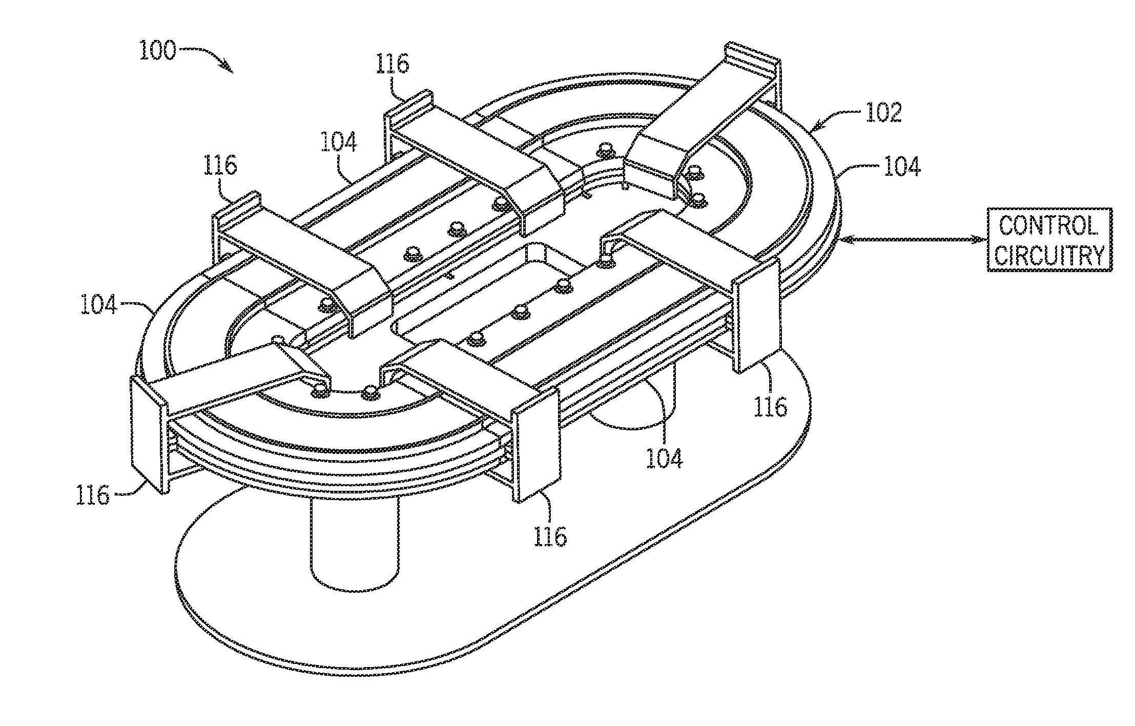
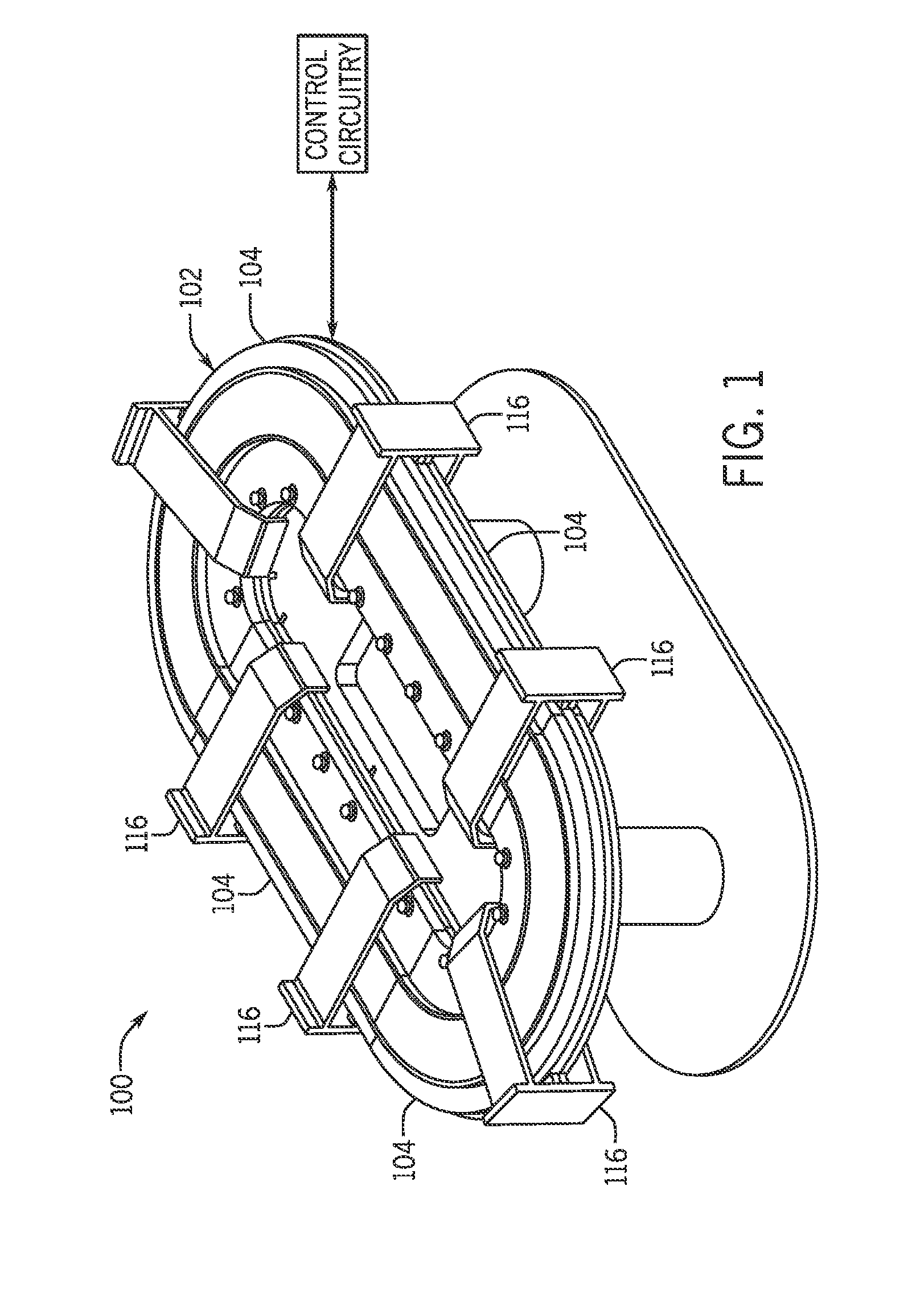
[0027]The present disclosure relates to a linear controlled motion system, such as a system having a track formed from one or more track sections, and having at least one mover mounted to the track and effective for receiving articles at one location and transporting the articles to another location. The system includes at least one magnetic linear motion motor for providing a magnetic field effective for moving each mover in a controlled motion along the track. Preferably, the controlled motion system includes a magnetic flux bridge for reducing changes in the magnetic flux that would otherwise reduce the efficiency or interfere with the operation of the controlled motion system. In the present disclosure, specific terminology will be resorted to for the sake of clarity. However, the technology and concepts are not intended to be limited to the specific terms so selected, and it is to be understood that each specific term includes all technical equivalents that operate in a similar...


PUM


Abstract

A linear controlled motion system comprises a track formed from one or more track sections and having at least one mover mounted to the track and effective for receiving articles at one location and transporting the articles to another location. The system includes at least one magnetic linear motion motor for providing a magnetic field effective for moving each mover in a controlled motion along the track and a magnetic flux bridge for reducing changes in the magnetic flux that reduces the efficiency or interferes with the operation of the controlled motion system.

Description

CROSS REFERENCE TO RELATED APPLICATIONS[0001]This application is a Non-Provisional Patent Application of U.S. Provisional Patent Application No. 61 / 792,150, entitled “Controlled Motion System Having a Magnetic Flux Bridge Joining Linear Motor Sections”, filed Mar. 15, 2013, which is herein incorporated by reference.BACKGROUND[0002]The present invention relates generally to controlled motion systems and more specifically, the present invention relates to controlled motion systems having more than one linear motor sections and means of joining the linear motor sections together using a magnetic flux bridge such that the likelihood of interruption or a change in the level of magnetic flux along and between the linear drive sections is reduced.[0003]The application of controlled motion systems to a wide variety of processes (e.g. for packaging, transporting objects, assembly automation, and processes involving use of machine tools, etc.) provides the advantage of increasing both the spe...

Claims


Application Information

Patent Timeline
Patent Type & Authority Applications(United States)
IPC IPC(8): H02K41/02H02K1/12
CPCH02K1/12H02K41/02H02K41/031H02K1/148H02K1/14H02K2201/15B65G54/02
Inventor JACOBS, KEITH G.WERNERSBACH, GLEN C.
Owner ROCKWELL AUTOMATION
Why Eureka
Try Eureka