LNA with Linearized Gain Over Extended Dynamic Range

Active Publication Date: 2014-09-18
INNOPHASE
View PDF8 Cites 31 Cited by
  • Summary
  • Abstract
  • Description
  • Claims
  • Application Information

AI Technical Summary

Problems solved by technology

Otherwise, the signal to noise ratio (SNR) of th

Method used


Image

  • LNA with Linearized Gain Over Extended Dynamic Range
  • LNA with Linearized Gain Over Extended Dynamic Range
  • LNA with Linearized Gain Over Extended Dynamic Range

Examples


Embodiment Construction

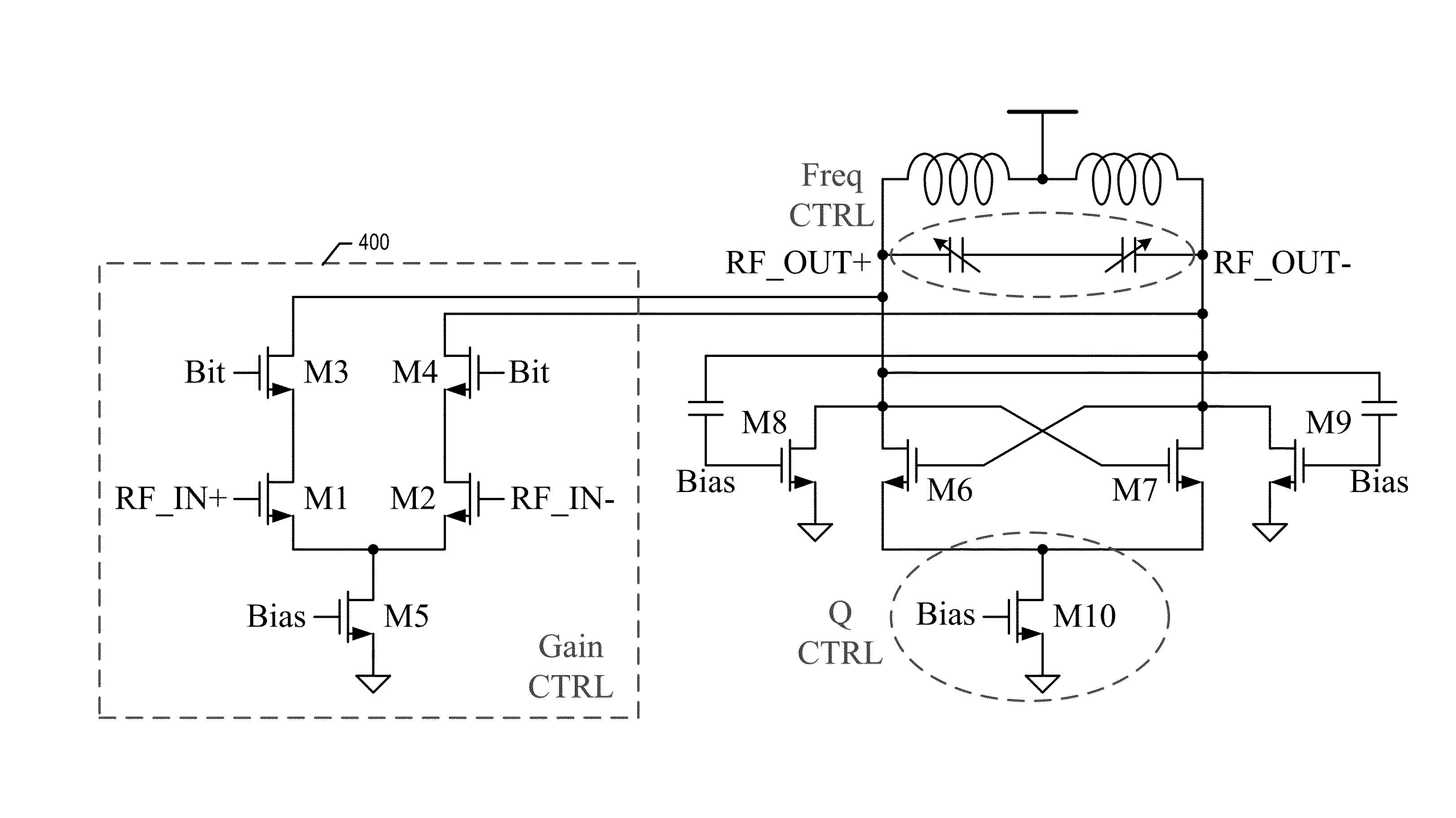
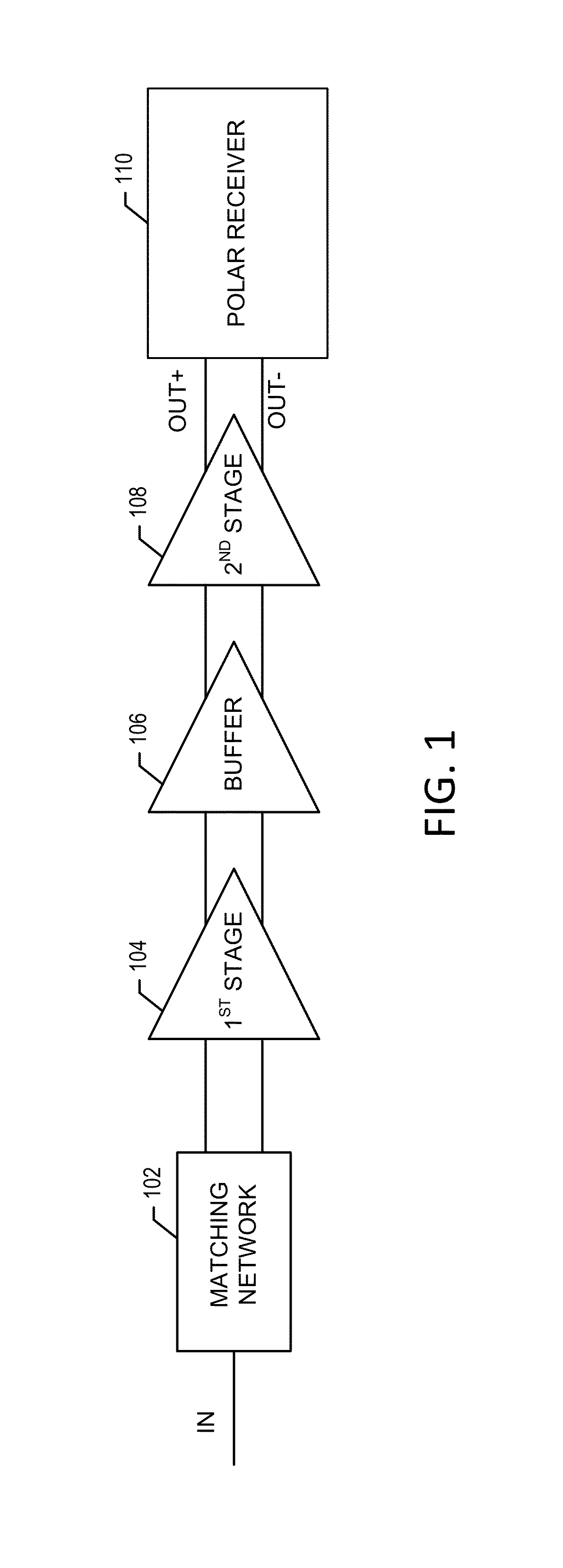
[0018]With reference to FIG. 1, an embodiment of a low noise amplifier in accordance with some embodiments will be described. A received signal, such as from an antenna, is received by the matching network 102. The output of the matching network is provided to the first LNA stage 104, the output of which is connected via buffer 106 to the second LNA stage 108. The buffer circuit is depicted in FIG. 6.

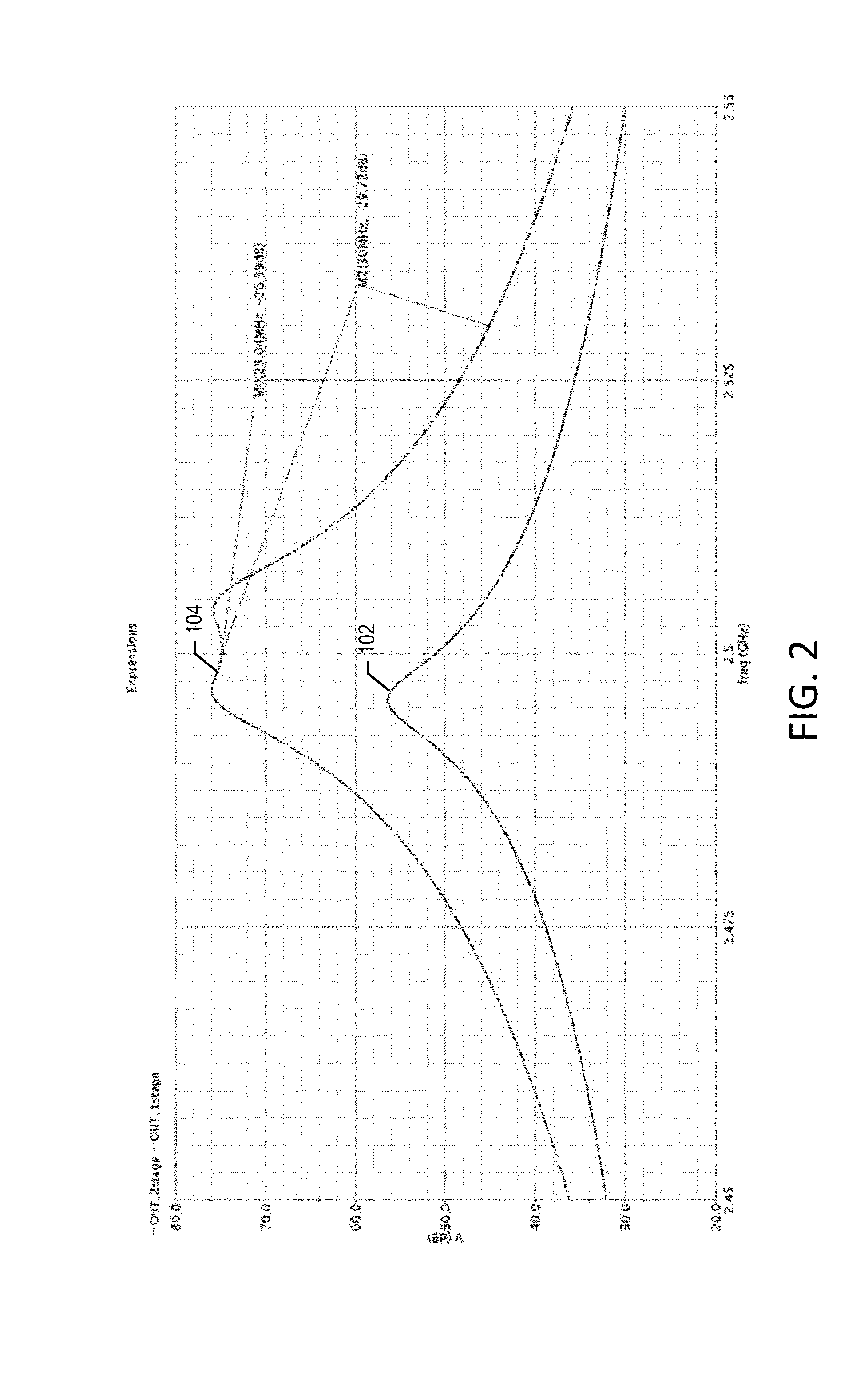
[0019]The output of the cascaded LNA stages is further processed in a receiver, such as a polar receiver 110. Additional details of the polar receiver may be found in the co-pending application Attorney Docket 71601.US.01 filed Mar. 15, 2013, entitled POLAR RECEIVER SIGNAL PROCESSING AND ARCHITECTURE. Other well-known receiver architectures may also be used. Each stage of the two LNA stages 104, 108 may be tuned to exhibit a bandpass response. The two center frequencies, one from each stage, may be offset to provide an overall wider frequency bandwidth, yet still providing a high degree...


PUM


Abstract

A low noise amplifier including a variable gain amplifier stage configured to accept an input signal and to provide a load driving signal; a tunable bandpass filter connected as a load to the variable gain amplifier stage, wherein the bandpass filter includes a cross-coupled transistor pair, and at least one cross-coupled compensation transistor pair biased in a subthreshold region configured to add a transconductance component when the load driving signal is of a magnitude large enough to decreases a transconductance of the cross-coupled transistor pair; and, a controller circuit configured to tune the bandpass filter. The filter can be tuned in respect to the frequency and the quality factor Q.

Description

CROSS REFERENCE TO RELATED APPLICATIONS[0001]This application is related to the following co-pending applications, filed on even date herewith, all of which are incorporated herein by reference in their entirety: Attorney Docket 71601.US.01 filed Mar. 15, 2013, entitled POLAR RECEIVER SIGNAL PROCESSING AND ARCHITECTURE; Attorney Docket 71602.US.01, filed Mar. 15, 2013, entitled POLAR RECEIVER SIGNAL PROCESSING APPARATUS AND METHODS; Attorney Docket 71604.US.01 filed Mar. 15, 2013, entitled DIGITALLY CONTROLLED INJECTION LOCKED OSCILLATOR; and, Attorney Docket 71605.US.01, filed Mar. 15, 2013, entitled SINGLE-BIT DIRECT MODULATION TRANSMITTER.BACKGROUND OF THE INVENTION[0002]Low Noise Amplifiers are circuits for amplifying weak signals such as those received from antennas. It is important that they not introduce much noise given the weak power levels of the received signal. Otherwise, the signal to noise ratio (SNR) of the signal would be unacceptable for data recovery. The effect of...

Claims


Application Information

Patent Timeline
IPC IPC(8): H03G3/00
CPCH03G3/008H03G5/14H03G1/0029H03G1/0088H03G5/24
Inventor TESTI, NICOLOLI, XIZHANG, XUEJUNXU, YANG
Owner INNOPHASE
Why Eureka
Try Eureka