Ring oscillator circuit and method

Active Publication Date: 2014-09-18
QUALCOMM INC
View PDF5 Cites 11 Cited by
  • Summary
  • Abstract
  • Description
  • Claims
  • Application Information

AI Technical Summary

Benefits of technology

The patent discusses a new type of voltage controlled oscillator (VCO) that is more stable, has less noise, and uses less power than traditional methods. This is useful for creating more reliable and efficient circuitry.

Problems solved by technology

However, the large capacitor can introduce a “pole” at a particular frequency on the feedback path, potentially resulting in instability of the system and causing the output of the regulator to oscillate.
The replica reduces capacitor-induced instability that may otherwise be caused by the capacitor, but the replica may introduce noise and may increase power consumption.

Method used


Image

  • Ring oscillator circuit and method
  • Ring oscillator circuit and method
  • Ring oscillator circuit and method

Examples


Embodiment Construction

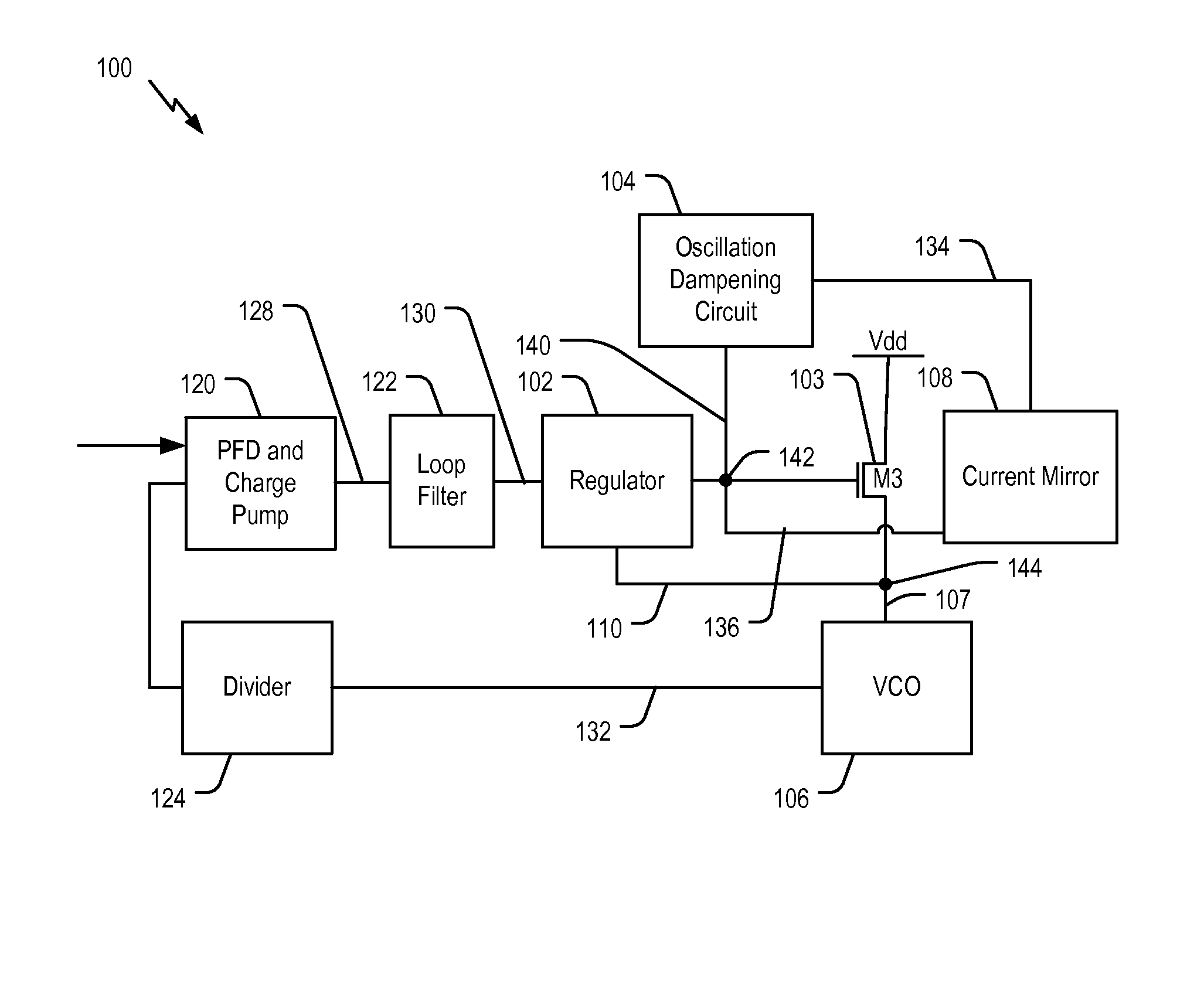
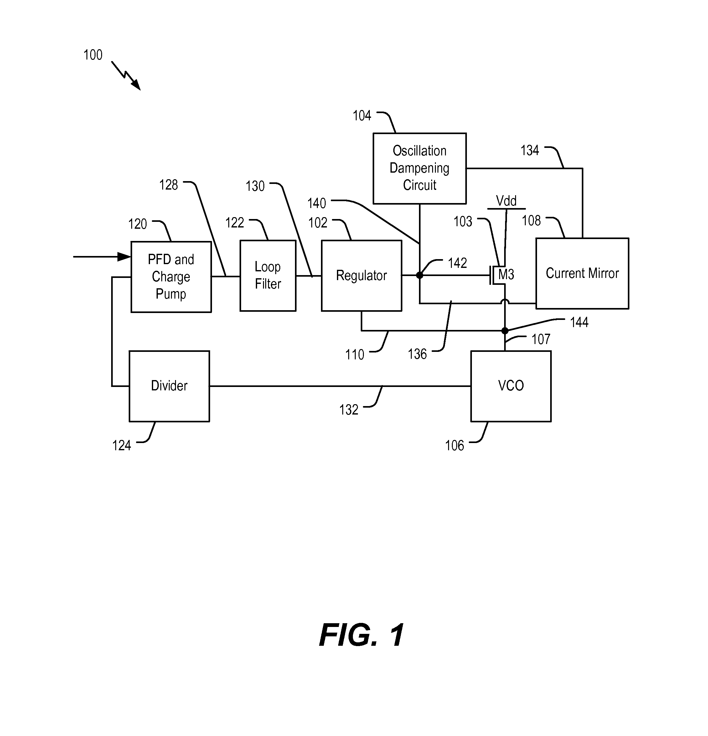
[0031]FIG. 1 illustrates a phase locked loop (PLL) 100 that includes a regulator 102 to regulate a supply voltage to a VCO 106. An oscillation dampening circuit 104 is coupled to an output of the regulator 102 to substantially dampen or cancel oscillations that may otherwise occur at the output of the regulator 102. The oscillation dampening circuit 104 enables stable operation of the regulator 102 without use of a replica VCO.

[0032]The PLL 100 includes a phase-frequency detector (PFD) and charge pump 120 that is configured to receive a reference signal 118 having a reference frequency (Fref) and to receive the PLL feedback signal 126 from a divider 124. The PFD and charge pump 120 is configured to provide an output 128 based on a detected phase or frequency difference between the reference signal and the PLL feedback signal. The output 128 of the PFD and charge pump 120 is provided to a loop filter 122. The loop filter 122 is configured to provide a filtered signal 130 to the regul...


PUM


Abstract

Oscillator circuits and methods are disclosed. In an embodiment, a circuit includes a voltage controlled oscillator (VCO) and a regulator coupled to a supply input of the VCO. The circuit also includes an oscillation dampening circuit coupled to an output of the regulator. A resistance or a capacitance of the oscillation dampening circuit is configured to vary based on current provided to the VCO.

Description

I. FIELD[0001]The present disclosure is generally related to oscillators, more particularly to supply regulated ring oscillators.II. DESCRIPTION OF RELATED ART[0002]Ring oscillators may be used to provide an oscillating output signal. An oscillation frequency of the output signal is responsive to a voltage supply range that is provided to the ring oscillator. The ring oscillator operates as a voltage controlled oscillator (VCO). A large capacitance is typically used to filter high-frequency noise from the voltage supply of the VCO. In addition, a regulator is typically used to provide the voltage supply to the VCO. The regulator can have a feedback path from the VCO to adjust an output of the regulator. However, the large capacitor can introduce a “pole” at a particular frequency on the feedback path, potentially resulting in instability of the system and causing the output of the regulator to oscillate.[0003]A conventional technique to avoid the potential instability resulting from...

Claims


Application Information

Patent Timeline
IPC IPC(8): H03K3/03
CPCH03K3/0315H03L7/0995H04L7/033
Inventor HINRICHS, JEFFREY MARKCHEN, LUIS
Owner QUALCOMM INC
Why Eureka
Try Eureka