Kneading apparatus
a technology of kneading apparatus and kneading object, which is applied in the direction of clay mixing apparatus, rotary stirring mixer, transportation and packaging, etc. it can solve the problems of affecting the uniform kneading of the entire material, the conventional kneading apparatus, etc., and achieves the effect of increasing the staying time of the kneaded object, increasing the lump-crushing effect, and increasing the time of the material
- Summary
- Abstract
- Description
- Claims
- Application Information
AI Technical Summary
Benefits of technology
Problems solved by technology
Method used
Image
Examples
embodiment 1
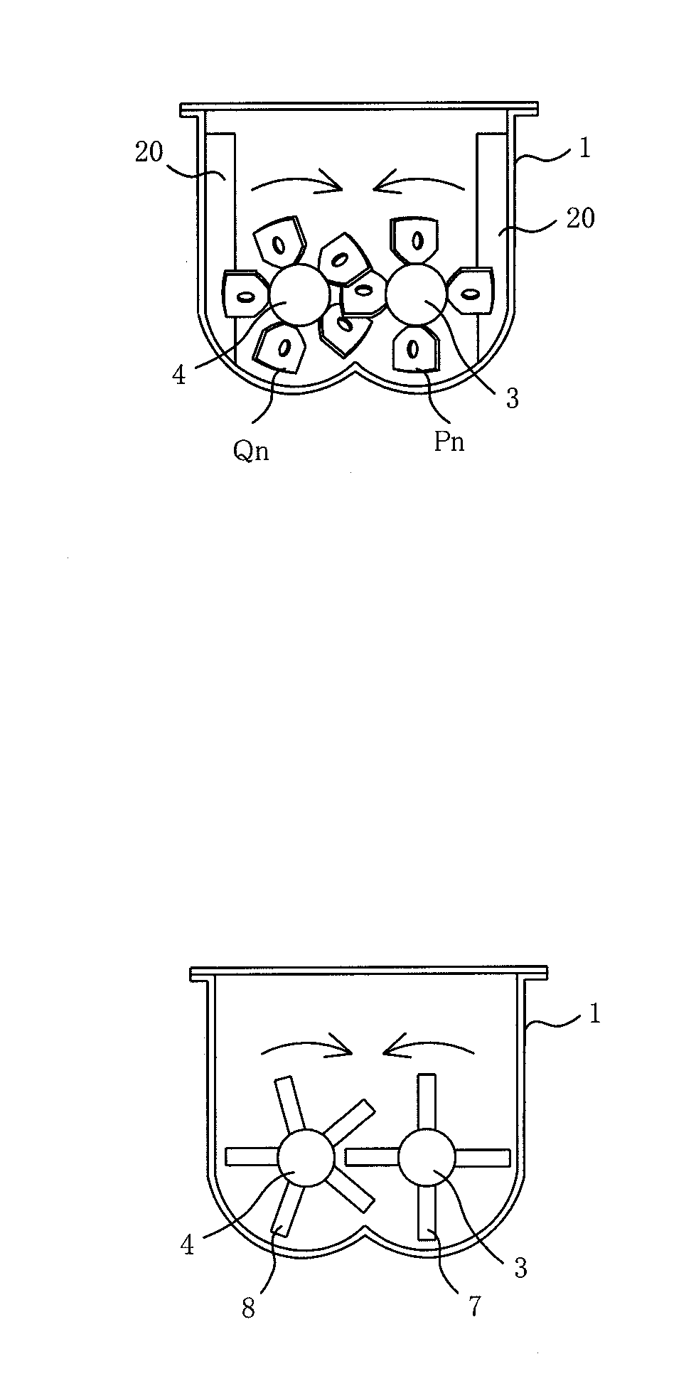
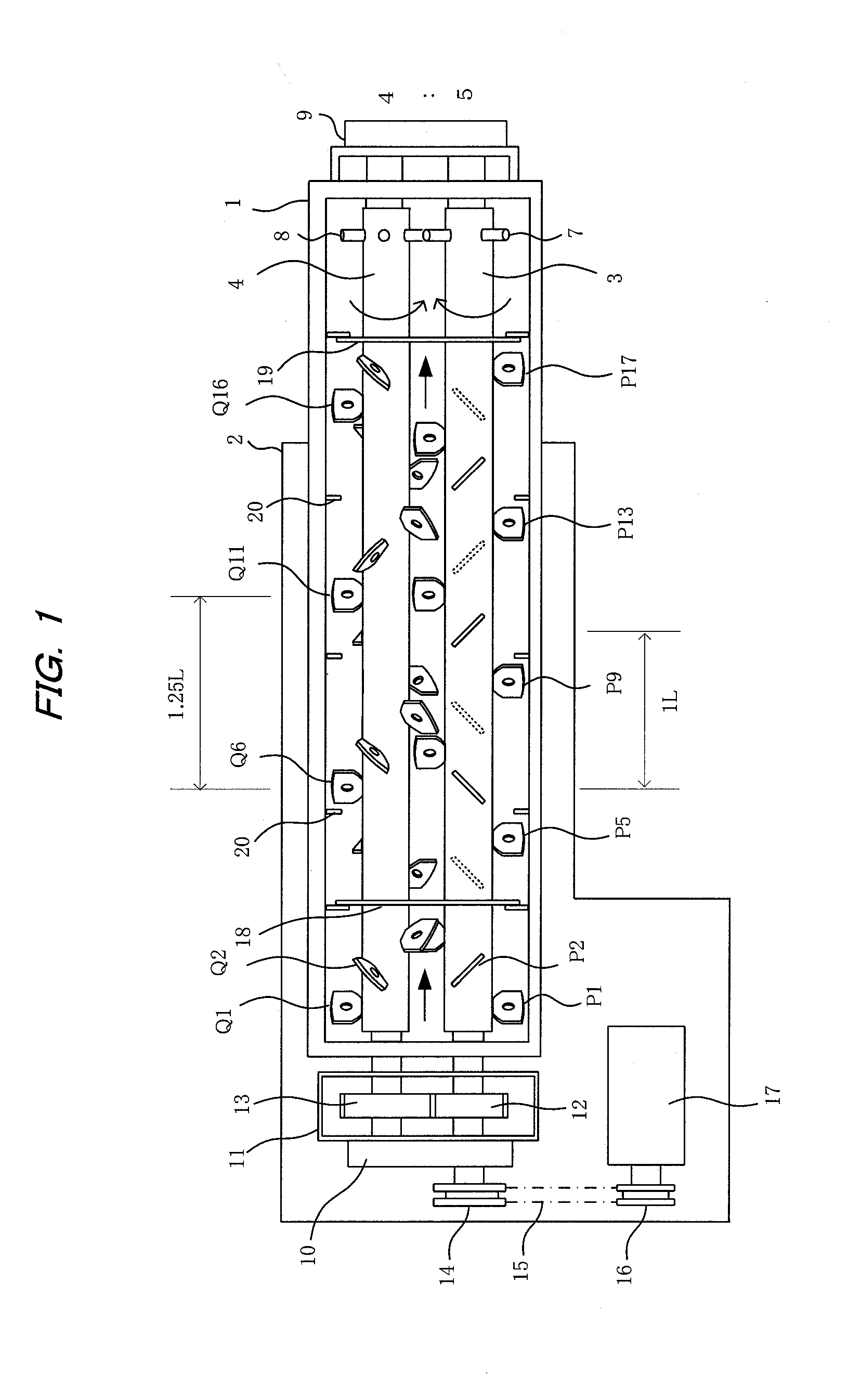
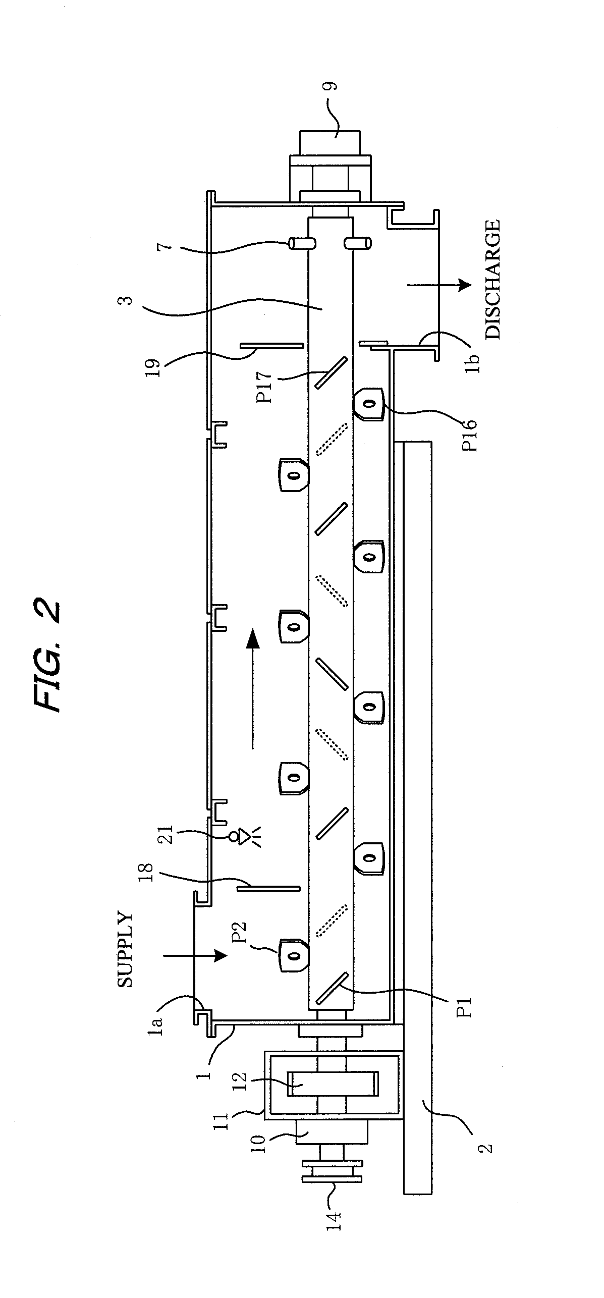
[0043]FIGS. 1 through 4 show the structure of a kneading apparatus according to Embodiment 1 of the present invention. FIG. 1 is a top view showing the kneading apparatus with a large part of the top of the housing removed therefrom, FIG. 2 is a side view along one rotary shaft in the housing of the kneading apparatus, FIGS. 3a and 3b are cross-sectional views orthogonal to the rotary shafts, showing the paddles and rods of the rotary shafts provided in the kneading apparatus, and FIG. 4 is an illustrative view showing the arrangement of paddles when the rotary shafts are viewed from the directions A to D (A to E).
[0044]In FIGS. 1 through 4, reference numeral 1 indicates a housing of the kneading apparatus, which is provided horizontally on a base frame 2. The housing 1 is formed into a long, thin, rectangular parallelepiped shape. At the top of the left end shown in FIG. 2, a supply opening 1a is provided for supplying (dropping in) material (powdery or granular material) to be kne...
embodiment 3
[0079]FIGS. 10 and 11 show an embodiment in which flat phase paddles are provided having paddle surfaces oriented along the axial direction of the rotary shafts 3, 4, and the cyclically repeating sequence as viewed in the axial direction is normal, flat, and reverse. In FIG. 11, (S) indicates a flat phase paddle.
[0080]The normal phase paddles P2, P5, P8, P11, P14, P17 on the rotary shaft 3 and the normal phase paddles Q2, Q5, Q8, Q11, Q14, Q17 on the rotary shaft 4 in Embodiment 1 are made to have flat phases. In this embodiment, the kneaded object conveying force is reduced because the kneaded object fed by the normal phase paddles passes by the next flat phase paddles and is pushed back by the next reverse phase paddles. The stirring time increases in proportion to the reduction in conveying force, and the kneading degree is significantly improved. To increase the conveying force, the normal phase paddles are attached so that the paddle surfaces align along the helix, the reverse ...
PUM
| Property | Measurement | Unit |
|---|---|---|
| rotation | aaaaa | aaaaa |
| angle | aaaaa | aaaaa |
| angle | aaaaa | aaaaa |
Abstract
Description
Claims
Application Information
 - R&D
- Intellectual Property
- Life Sciences
- Materials
- Tech Scout
- Unparalleled Data Quality
- Higher Quality Content
- 60% Fewer Hallucinations
Browse by: Latest US Patents, China's latest patents, Technical Efficacy Thesaurus, Application Domain, Technology Topic, Popular Technical Reports.
© 2025 PatSnap. All rights reserved.Legal|Privacy policy|Modern Slavery Act Transparency Statement|Sitemap|About US| Contact US: help@patsnap.com


