Computer system and method for communicating data between computers

a computer system and data communication technology, applied in the field of computer system and method for communicating data between computers, can solve the problems of increasing the cost of installation of facilities, large amount of data communicated between servers in a data center,

Active Publication Date: 2014-09-18
HITACHI LTD
View PDF3 Cites 19 Cited by
  • Summary
  • Abstract
  • Description
  • Claims
  • Application Information

AI Technical Summary

Benefits of technology

[0012]According to the present invention, it is possible to achieve communication between severs by use of PCIe switches. Thus, the need for the use of network devices of Ethernet in the conventional computer system where servers are connected via Ethernet can be eliminated. Further, when the communication between servers is achieved by use of PCIe switches, data communication is possible between servers by the existing software for the communication between servers using Ethernet.

Problems solved by technology

In general, the amount of data communicated between servers in a data center is large, and there is a problem of increasing the cost of the installation of facilities such as network switches, cables, and Ethernet cards for communication via Ethernet.

Method used


Image

  • Computer system and method for communicating data between computers
  • Computer system and method for communicating data between computers
  • Computer system and method for communicating data between computers

Examples


example 1

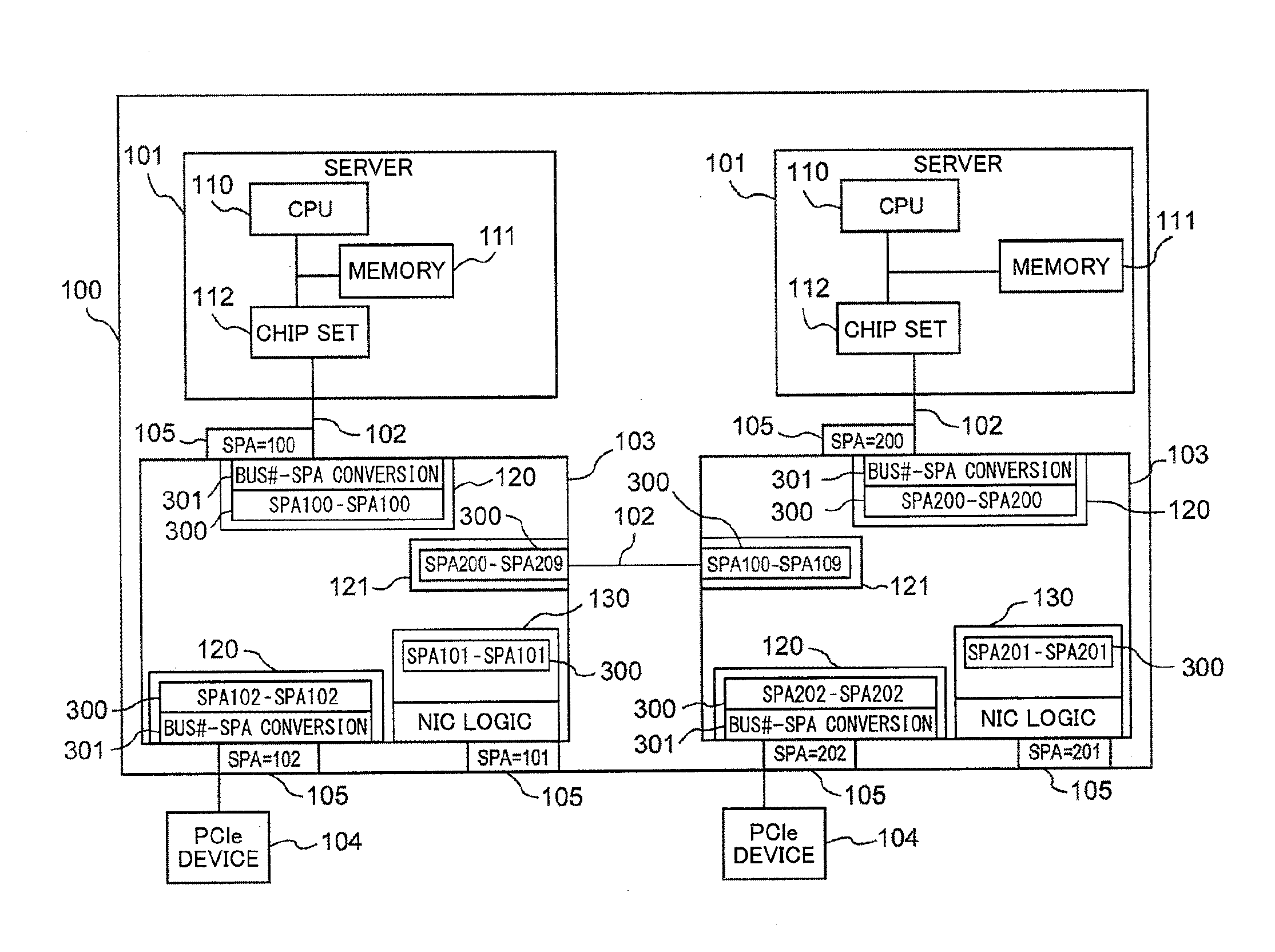
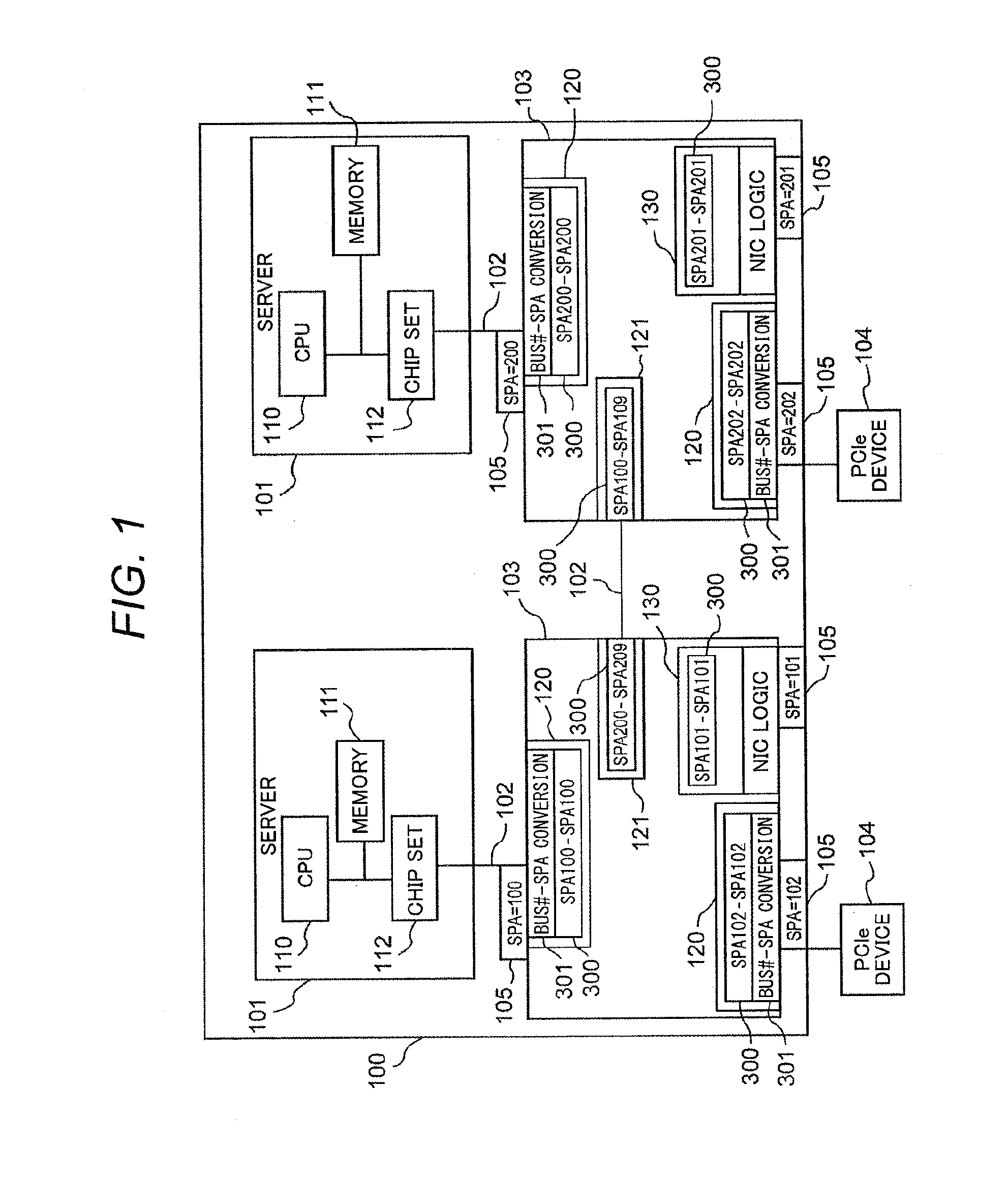
[0033]FIG. 1 is an overall block diagram of a computer system according to an example of the present invention. A computer system 100 includes: multiple servers 101 each including a CPU 110, a memory 111, and a chip set 112 to execute programs under an OS (operating system); multiple switches (PCIe switches) 103 based on the PCIe standard, which are connected to each of the servers 101 through a PCIe link 102; and an I / O device (hereinafter, referred to as a PCIe device) 104 based on the PCIe standard, which is connected to the PCIe switch 103.

[0034]The PCIe switch 103 includes a port for connecting the server, the PCIe device, and another PCIe switch. The port has two types: a port 120 (which is referred to as an external port) connected to the server 101 and the PCIe device 104 through the PCIe link; and a port 121 (which is referred to as an internal port) connected to another PCIe switch through the PCIe link. A system port address (SPA) 105 is allocated to the external port 120...

example 2

[0067]The present example shows an example where multiple servers are connected to a single PCIe switch with multiple VLANs (Virtual LANs) present in a computer system.

[0068]FIG. 9 is an overall block diagram of a computer system. In a computer system 100 shown in FIG. 9, the same reference numerals as those shown in FIG. 1 of Example 1 have the same components and functions. The description of these components will be omitted to avoid redundancy. In FIG. 9, the difference from the configuration in FIG. 1 is that multiple servers 101 are connected to a single PCIe switch 103, and that the NIC logic 130 includes a SUB_ALCMAP (Sub Address Allocation Map) 302, a VLAN_MAP 303, a broadcast routing table 304, and an INUA 305. The NUA is a unique number in the system that is allocated to each NIC logic to identify each NIC logic from others. In addition, the field of the Bus#-SPA conversion table 301 is extended.

[0069]FIG. 10 is a schematic block diagram of the computer system to illustrat...


PUM


Abstract

In a computer on the transmission side, an NW driver, which is recognized, by the OS, as an NIC driver, stores data to be transmitted and a destination SPA into a memory, and outputs a transaction layer packet (TLP), which has been generated by a first computer, to a PCIe switch. A first NIC logic of the PCIe switch of the PCIe switch corresponding to the first computer on the transmission side adds a system port address (SPA) to the TLP transferred from the first computer, and transfers the data of the TLP to a port associated with a second NIC logic and having an address indicated by the SPA (destination SPA). The second NIC logic having received the data writes the receive data into a memory of a second computer, on the reception side, which is connected to another PCIe switch where the second NIC logic exists.

Description

TECHNICAL FIELD[0001]The present invention relates to a computer system and method for communicating data between computers, and more particularly, to data communication between servers connected by use of switches based on the PCI Express standard (that is hereinafter referred to as PCIe switches).BACKGROUND ART[0002]Ethernet (registered trademark) is mainly used as a communication method between servers in a data center. In general, the amount of data communicated between servers in a data center is large, and there is a problem of increasing the cost of the installation of facilities such as network switches, cables, and Ethernet cards for communication via Ethernet.[0003]Further, a PCIe switch is used as a communication tool between a high-speed server and a device connected to the server. For example, Patent Literature 1 discloses a computer system where multiple computers and multiple input / output devices are connected by a PCIe switch. Patent Literature 2 discloses a technolo...

Claims


Application Information

Patent Timeline
Patent Type & Authority Applications(United States)
IPC IPC(8): H04L12/935H04L49/111
CPCH04L49/30G06F13/4022
Inventor EGUCHI, SHUHEIYAMAGATA, RYOMURAKAMI, YOSHIKI
Owner HITACHI LTD
Why Eureka
Try Eureka