Ct system and detection device for ct system

a detection device and a technology for ct systems, applied in the field of ct systems and detection devices for ct systems, can solve the problems of excessive cost of manufacturing systems and huge requirements for detectors and data acquisition units of such systems, and achieve the effects of low cost of system manufacture, reduced requirements for detection and data acquisition units, and high system performan

Active Publication Date: 2014-09-18
NUCTECH CO LTD +1
View PDF2 Cites 0 Cited by
  • Summary
  • Abstract
  • Description
  • Claims
  • Application Information

AI Technical Summary

Benefits of technology

[0026]The present invention proposes surface-array arrangement of low-energy detectors and sparse arrangement of high-energy detectors. As a result, detectors and data acquisition units are greatly reduced. A high-resolution three-dimensional CT image is acquired while high-accuracy hazardous article alarm is achieved. The cost of manufacture of the system is greatly decreased while high system performance is ensured.

Problems solved by technology

Numbers of detectors and data acquisition units of such a system requires are enormous.
As a result, the cost for manufacturing the system is too high.

Method used


Image

  • Ct system and detection device for ct system
  • Ct system and detection device for ct system
  • Ct system and detection device for ct system

Examples


Embodiment Construction

[0032]A further description of the invention will be made as below with reference to embodiments of the present invention taken in conjunction with the accompanying drawings.

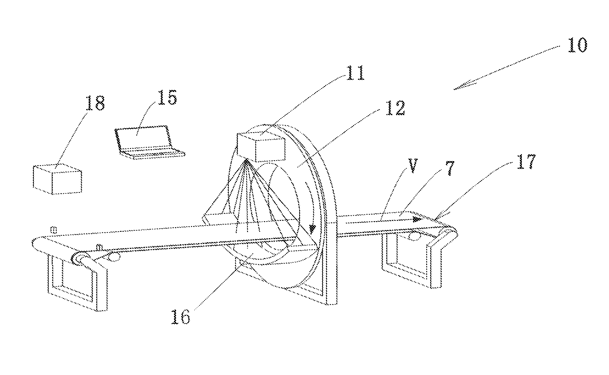
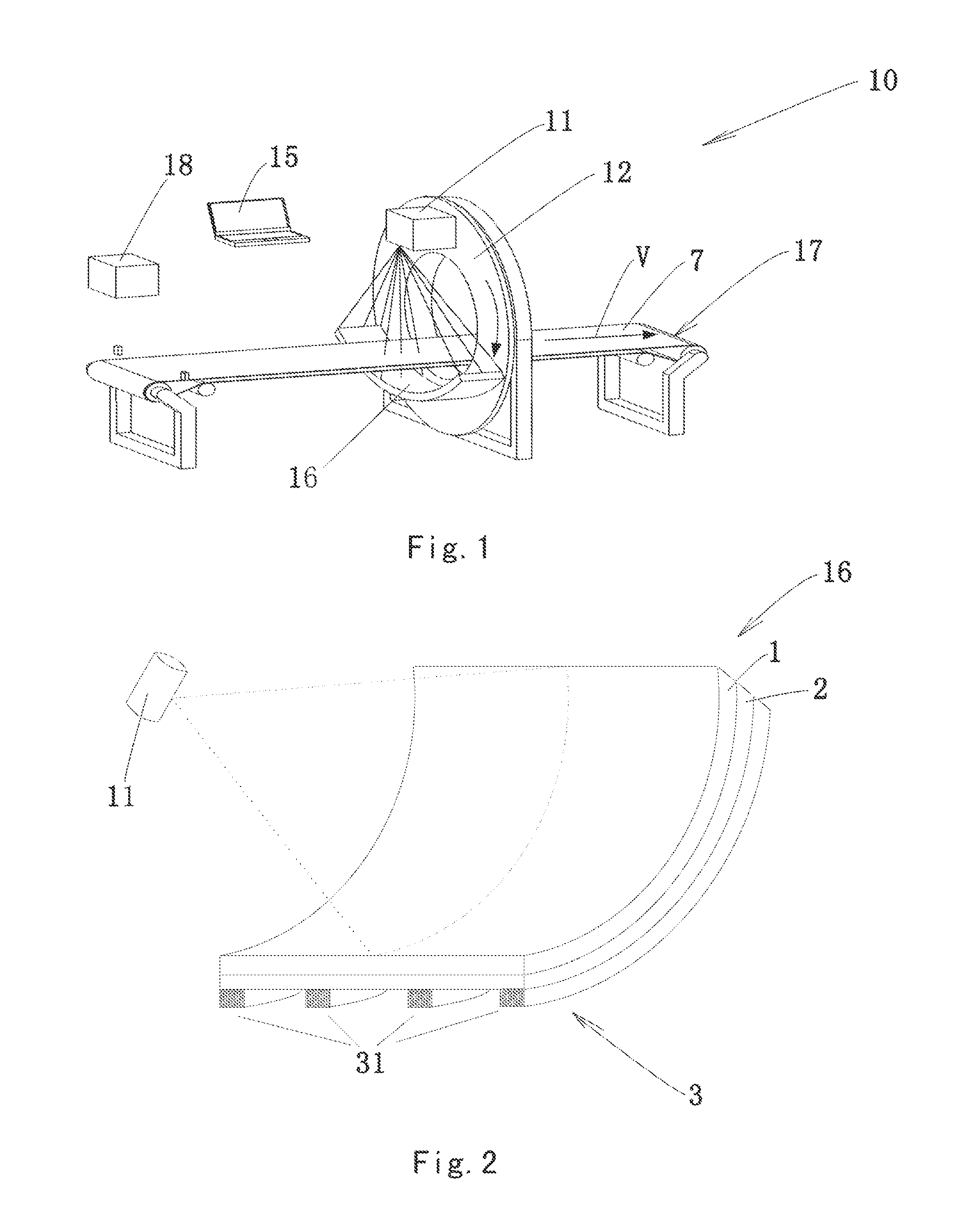
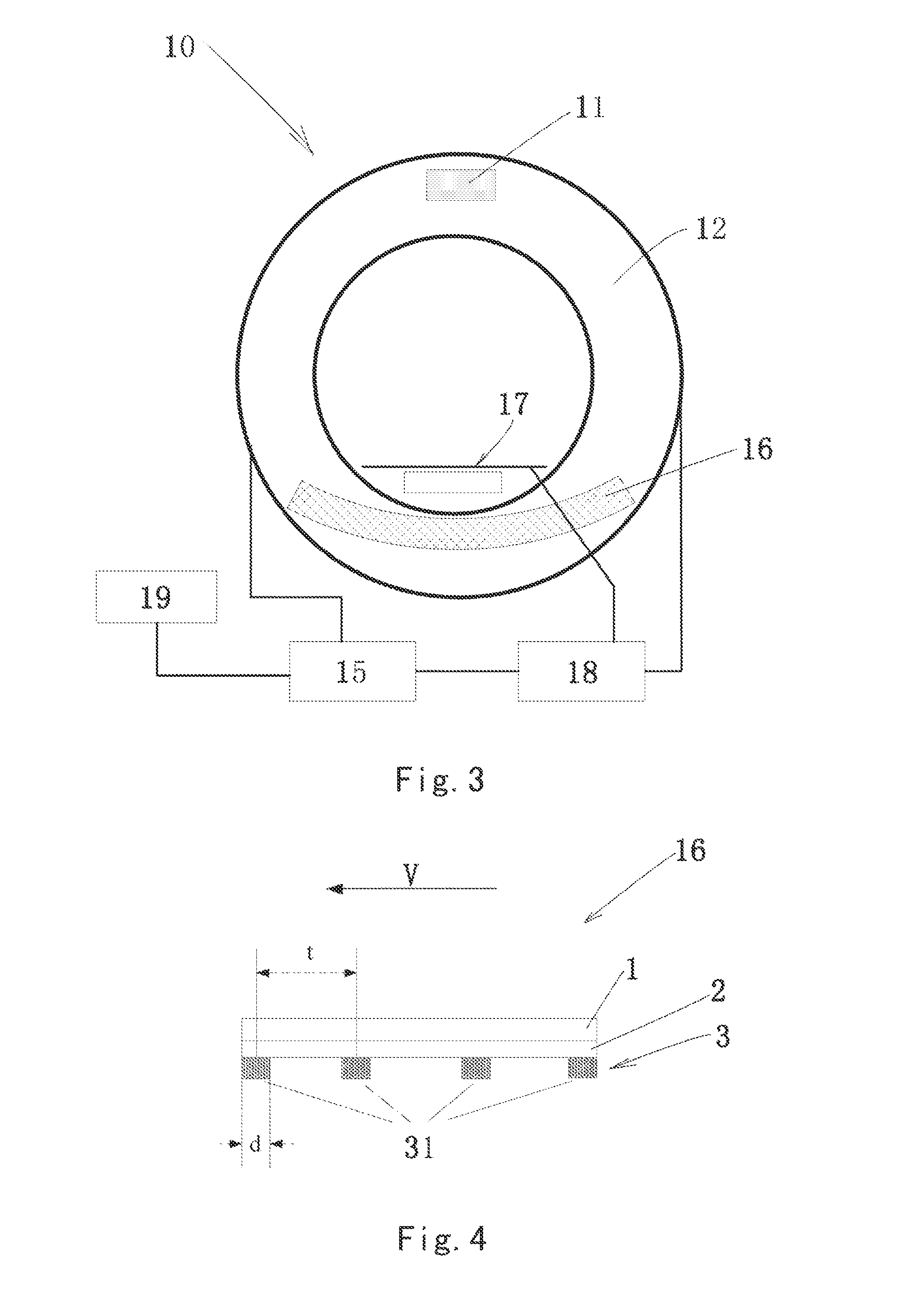
[0033]As shown in FIGS. 1 and 3, a CT system 10 according to an embodiment of the present invention comprises: a transfer device 17 for transferring an object under inspection in a transfer direction V; a gantry 12 rotatable about a rotational axis which may be substantially parallel to the transfer direction V; a ray source 11 connected to the gantry 12; a detection device 16 connected to the gantry 12 opposite the ray source 11 so that the detection device 16 and the ray source 11 can rotate together with the gantry 12, a control device 18 for controlling operation of the CT system 10; a data processing device 15 for processing data detected by the detection device 16; and an alarm device 19 for warning when there is a suspicious article in an object under inspection.

[0034]The ray source 11 may emit an X-ray. ...


PUM

PropertyMeasurementUnit
widthaaaaaaaaaa
widthaaaaaaaaaa
widthaaaaaaaaaa

Abstract

A detection device for a CT system comprises a low-energy detector assembly; and a high-energy detector assembly disposed under the low-energy detector assembly. The high-energy detector assembly comprises: a plurality of rows of high-energy detectors arranged at predetermined intervals. With the detection device, detectors and data acquisition units are greatly reduced. A high-resolution three-dimensional CT image is acquired while high-accuracy hazardous article alarm is achieved. The cost of manufacture of the system is greatly decreased while high system performance is ensured.

Description

BACKGROUND OF THE INVENTION[0001]1. Field of the Invention[0002]The present invention relates to a CT system and a detection device for the CT system.[0003]2. Description of the Related Art[0004]In order to solve the problem of a scanning speed of a CT system, in a conventional method, a surface-array detector is adopted so that data can be acquired in rows simultaneously every time to improve the scanning speed. With requirement for a high accuracy of identification of hazardous articles in the field of safety inspection, a demand for dual-energy technique becomes increasingly desirable. In order to achieve high-speed scan and a high-resolution three-dimensional dual-energy image, conventionally a surface-array arrangement is adopted in both a high-energy detector and a low-energy detector. Numbers of detectors and data acquisition units of such a system requires are enormous. As a result, the cost for manufacturing the system is too high.SUMMARY OF THE INVENTION[0005]It is an obje...

Claims


Application Information

Patent Timeline
Patent Type & Authority Applications(United States)
IPC IPC(8): G01T1/16G01N23/04
CPCG01N23/046G01T1/16G01N2223/419G01N2223/643G01V5/0041H01L27/14601H01L27/14634H01L27/14658H01L27/14676H01L27/14806H01L27/14812A61B6/4241A61B6/482A61B6/542A61B6/0487G01T1/242
Inventor ZHANG, LICHEN, ZHIQIANGLI, YUANJINGLI, MINGLIANG
Owner NUCTECH CO LTD
Why Eureka
Try Eureka