Cordless telephone system and safety management system

Active Publication Date: 2014-09-18
PANASONIC INTELLECTUAL PROPERTY MANAGEMENT CO LTD
View PDF10 Cites 8 Cited by
  • Summary
  • Abstract
  • Description
  • Claims
  • Application Information

AI Technical Summary

Benefits of technology

The present invention aims to address the problems in the prior art by providing a cordless telephone system that can reliably detect halted or wandering behavior without the need for a special sensor. This system has a simple structure and does not require any special modules in the handset.

Problems solved by technology

Thus, the cost of laying the lines and installing the management device tends to increase the total cost of the system.
The technology disclosed in JP2004-118362A also requires a large-scale configuration including the multiple antennas and wireless communication server, and thus, tends to be so expensive that cannot be purchased easily by personal users.
The technology disclosed in JP2007-102441A uses the data communicated between the terminal device and the management device when the terminal device is connected to the network and the position information from the GPS or the like, and thus, the system also cannot be purchased easily by personal users.

Method used


Image

  • Cordless telephone system and safety management system
  • Cordless telephone system and safety management system
  • Cordless telephone system and safety management system

Examples


first embodiment

[0045]In the following, a first embodiment of the present invention will be described with reference to the appended drawings.

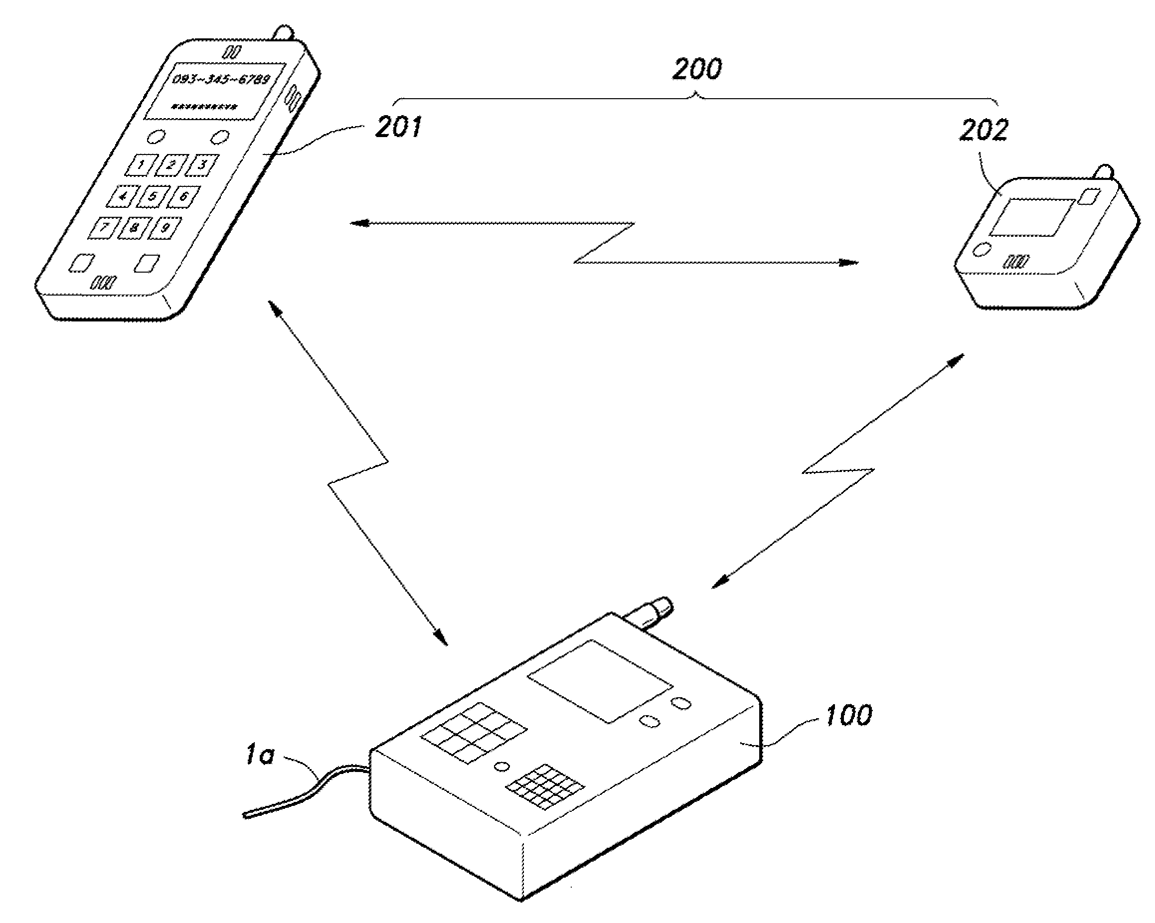
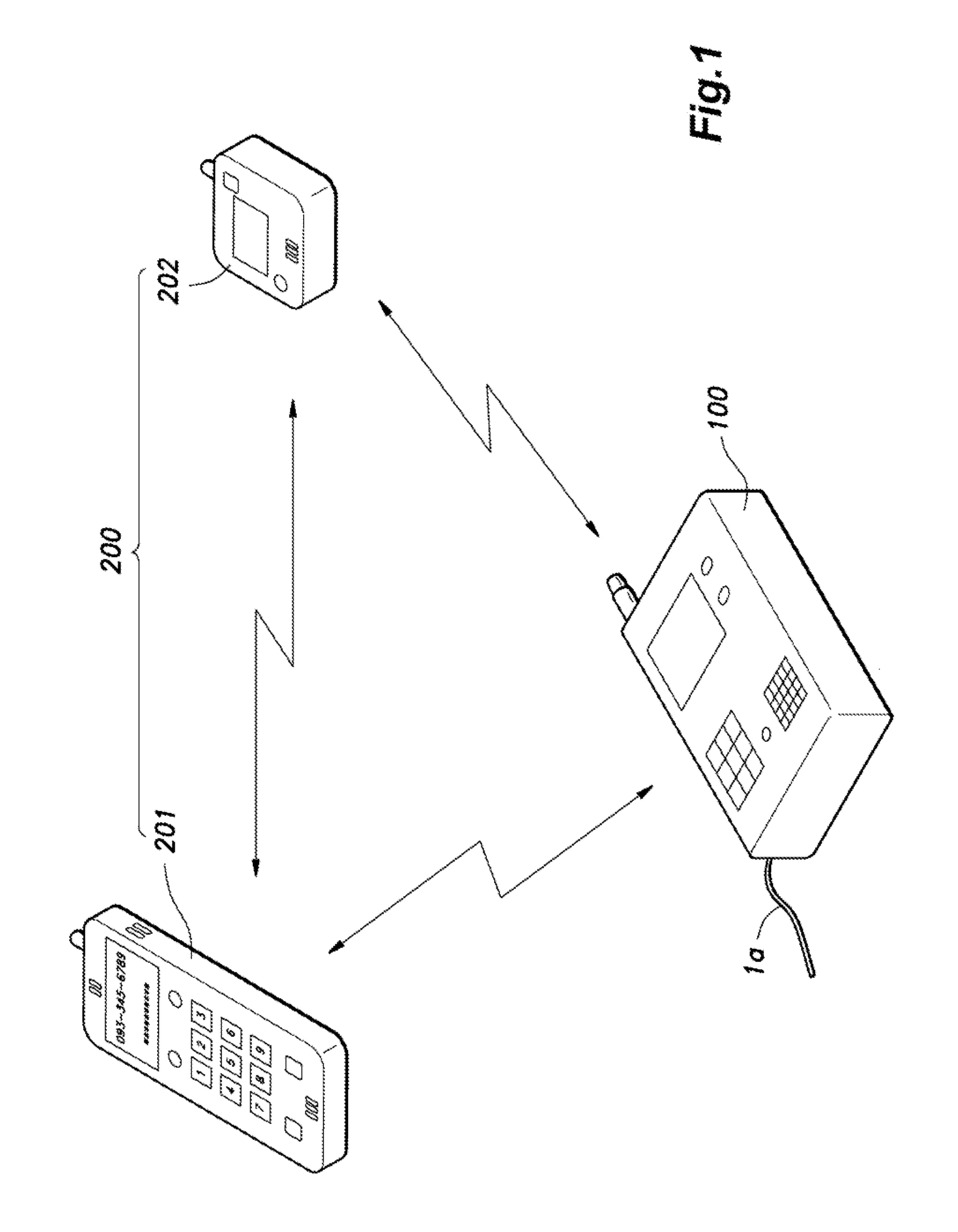
[0046]FIG. 1 is an explanatory diagram showing a relationship between a base unit 100, a first handset 201 and a second handset 202 of a cordless telephone system according to the first embodiment. As shown in FIG. 1, the cordless telephone system is constituted of a base unit 100 and two handsets 200 (first handset 201 and second handset 202). In the following description, when it is not necessary to distinguish between the first handset 201 and the second handset 202, they may be referred to as the handset(s) 200. It is to be noted that the number of the handsets 200 that can be included in the system is not limited to two, and the cordless telephone system may include three or more handsets 200, for example.

[0047]The base unit 100 is connected to a public telephone line not shown in the drawings via a telephone line la, and communicates audio data with ano...

second embodiment

[0121]In the following, a second embodiment of the present invention will be described with reference to the appended drawings.

[0122]In the first embodiment, monitoring is performed between the base unit 100 and the second handset 202. In the second embodiment, monitoring is performed using the radio waves transmitted and received between the first handset 201 and the second handset 202. Specifically, the second handset 202 is configured to receive control data transmitted from the first handset 201 in the control slot that is set for communication between the first handset 201 and the second handset 202, and the second handset 202 measures the RSSI signal when it receives data for monitoring, to detect an abnormality based on the measured RSSI signal. It is to be noted that the second embodiment assumes the situation shown in FIG. 7B, and the first handset 201 performs the role of the base unit 100 described in the first embodiment.

[0123]FIG. 12 is an explanatory diagram showing a ...

third embodiment

[0132]In the following, a third embodiment of the present invention will be described with reference to the appended drawings.

[0133]In the second embodiment, monitoring is performed using the first handset 201 and the second handset 202. Namely, the first handset 201 transmits the control data to the second handset 202 in the control slot, and when the second handset 202 detects an abnormality when it received the control data, the second handset 202 transmits data indicating the detection of an abnormality to the first handset 201. In the third embodiment, when an abnormality is detected by the second handset 202 that measures the RSSI signal, the detection of an abnormality is first notified from the second handset 202 to the first handset 201, and then, from the first handset 201 to the base unit 100.

[0134]FIG. 13 is an explanatory diagram showing a mode of use of the slots used by the base unit 100, the first handset 201 and the second handset 202 of the cordless telephone syste...


PUM


Abstract

Provided is a cordless telephone system including a base unit (100) connected to a telephone line and a handset (200) configured to transmit and receive radio waves to and from the base unit via wireless channel, wherein the handset includes a strength measurement unit (20) configured to measure a radio wave strength when the radio waves transmitted by the base unit are received by the handset, and a control unit (10) configured to measure a distance between the base unit and the handset based on a result of measurement performed by the strength measurement unit and to perform a prescribed safety management action when the distance becomes larger than a predetermined value.

Description

TECHNICAL FIELD[0001]The present invention relates to a cordless telephone system having a safety management function of detecting and notifying that a person who needs supervision, such as an infant or an elderly person, has moved away from around a supervisor who supervises the person who needs supervision by a predetermined distance, and to a safety management system.BACKGROUND OF THE INVENTION[0002]People's interest in security is increasing every year. For example, attracting high attention is detection of wandering of patients with dementia, prevention of infant abduction, etc. (hereinafter, summarily referred to as “safety management.” Further, a safety management action refers to an action taken in relation to the safety management). As a system for performing such a safety management action, there is known a safety management system that includes a wandering sensor(s) as a main component thereof. In this safety management system, entering of a person carrying a transmitter ...

Claims


Application Information

Patent Timeline
IPC IPC(8): G08B21/22
CPCG08B21/22G08B21/0222G08B21/023G08B21/0247G08B21/0283
Inventor ASHIZUKA, TETSUYA
Owner PANASONIC INTELLECTUAL PROPERTY MANAGEMENT CO LTD
Why Eureka
Try Eureka