Microphone mounting method and apparatus

Inactive Publication Date: 2014-09-18
M KLEMME TECH CORP
View PDF1 Cites 12 Cited by
  • Summary
  • Abstract
  • Description
  • Claims
  • Application Information

AI Technical Summary

Benefits of technology

[0010]The spiral configuration of the microphone supports allows a resilient support. Making the supports out of glass-filled polymer helps reduce the transmission of vibration to the microphone, especially low frequency noise. The use of spaced-apart microphone supports provides a very stable microphone support. The use of positionable bases on each microphone support allows adjustment of the spacing between supports and allows the location of the supports along the length of the microphone body to be varied as desired. The movable supports also allow positioning the microphone within the windscreen and allows supporting different microphone bodies, differently. As desired, the base and its attached microphone may be easily and quickly removed and replaced with a different base and support. Fingers forming a diamond-shape enclosure open at one end allow ready insertion and removal of microphone bodies, especially microphone bodies having two circular sides joined by two opposing flat surfaces.
[0011]The cage portions use a ring-stiffened rib structure and that provides a very light frame to enclose the microphone and microphone supports when a windscreen cover is placed over the structure. The ring-stiffened rib structure also provides a very strong structure that resists movement under wind loads and that reduces creaking and noise. Locating the rings to keep the ribs slightly bent provides a spring-loaded structure that keeps the ribs resiliently urged against the rings and provides a continually stressed enclosure that further helps reduce creaking and noise generation by the enclosure. Using a resilient material for the cove

Problems solved by technology

But these prior art devices make it difficult to fasten the microphones to the support and inadequately reduce vibration which can distort microphone signals and cause other undesirable audio distortions and noises.
Unfortunately, may existing microphone supports have fixed dimensions so that a microphone is supported at one location and thus rotates or swings with movement of the support, causing distortion of the audio signal from the microphone and inadequate support of the microphone.
Supports that grip the microphone body at more than one location are difficult to use, take time to insert the microphone into the supports and are often bulky—resulting in large windscreens to enclose the microphone and supports.
Microphones used in sound recording studios are often so sensitive such that air from ventilation vents, wind and even mild breezes can cause noises that are picked up by the microphones or that distort recorded audio signals.
Enclosing the microphones in casings reduces wind noise and distortion, but reduces microphone sensitivity.
Further, the microphones are often used on long booms and the enclosures are heavy and difficult to maneuver or to fa

Method used


Image

  • Microphone mounting method and apparatus
  • Microphone mounting method and apparatus
  • Microphone mounting method and apparatus

Examples


Embodiment Construction

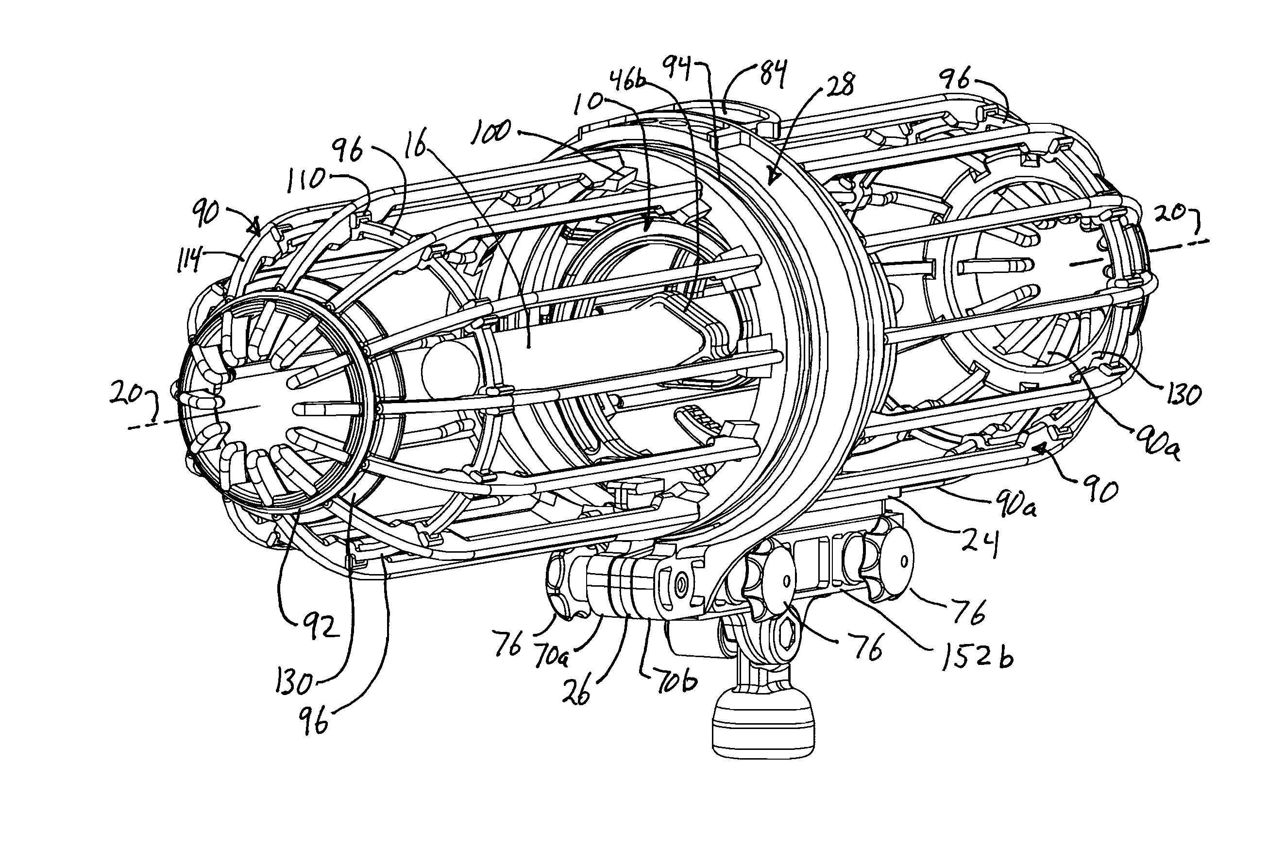
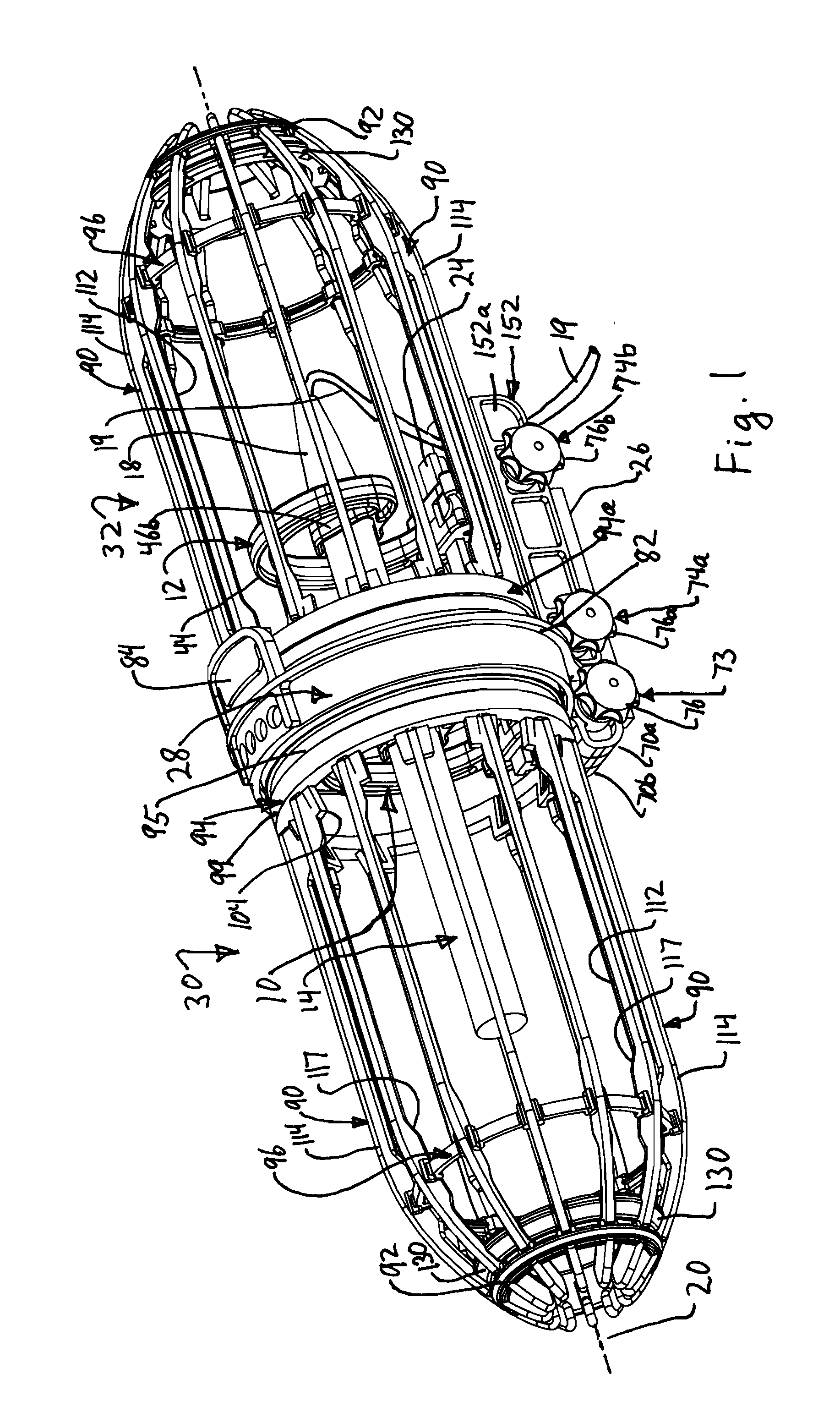
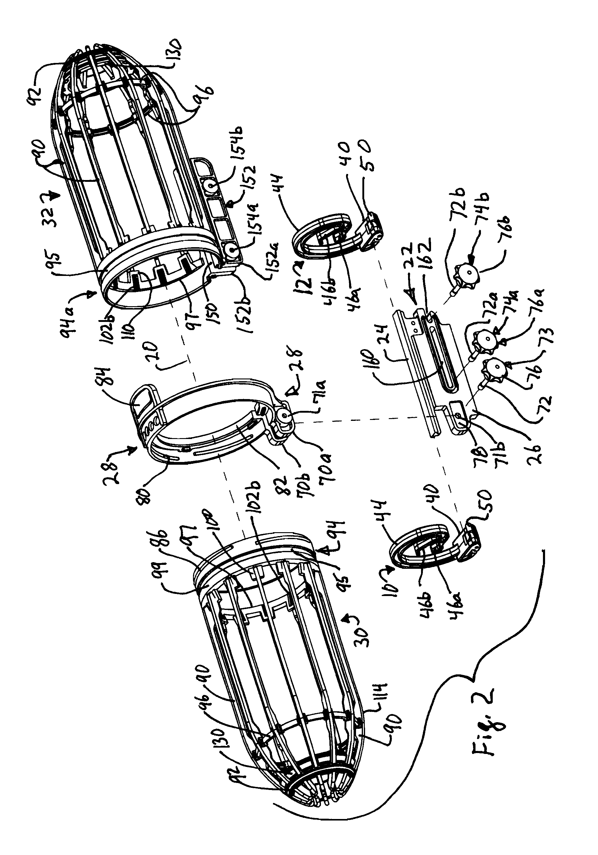
[0040]FIGS. 1-2 show first and second microphone supports 10, 12 which are spaced apart a distance sufficient to hold an elongated body of microphone 14 with a sensor end 18 and opposing cable end 16 from which optional communication cables connect to the microphone to carry electronic communication signals. The microphone extends along longitudinal axis 20 during use and may be a wireless microphone or transmit electronic signals relating to audio input through and electrically or optically conductive cord or cable 19 (FIG. 12). The supports are movably connected to an elongated connector 22 having an inner rail portion 24 and have what is preferably a generally flat piece extending radially outward from axis 20 forming an outer connecting portion 26. The relative directions and distances “inner” and “outer” are with reference to the longitudinal axis 20 of the actual or fictional microphone held by the supports 10, 12 during use.

[0041]A connecting bracket 28 is fastened to the elo...


PUM


Abstract

A microphone support and enclosing windscreen has microphone supports curving about 270 degrees about an axis with upper and lower fingers to grip the microphone above and below the longitudinal axis of the microphone. The microphone supports move along an upper rail of a connector. First and second cage portions have longitudinal ribs connected to circular rings forming a windscreen support, with base rings on each cage portion connected to a bracket to encircle the microphone and its supports during use. One of the cage portions moves along the connector and rotates to allow access to the microphone.

Description

STATEMENT RE: FEDERALLY SPONSORED RESEARCH / DEVELOPMENT[0001]Not ApplicableBACKGROUND[0002]Various structures have been provided to support microphones in ways that reduce the sensitivity of the microphone to vibrations and motion. But these prior art devices make it difficult to fasten the microphones to the support and inadequately reduce vibration which can distort microphone signals and cause other undesirable audio distortions and noises. There is thus a need for an improved microphone mount that allows easy and fast insertion and removal of the microphone and that deadens or reduces the sound transmission through the microphone support resulting from movement of the microphone or any windscreen enclosing the microphone.[0003]Microphones come in different sizes and lengths. Unfortunately, may existing microphone supports have fixed dimensions so that a microphone is supported at one location and thus rotates or swings with movement of the support, causing distortion of the audio...

Claims


Application Information

Patent Timeline
IPC IPC(8): H04R1/02
CPCH04R1/02H04R1/08H04R1/086
Inventor PARKER, BRENDA KLEMMECOREY, DAVID J.FISK, DAVID J.OUK, STEVE
Owner M KLEMME TECH CORP
Why Eureka
Try Eureka