
Method and related network element providing delay measurement in an optical transport network

a technology of optical transport network and delay measurement, applied in the field of telecommunications, can solve the problems of achieve the effect of improving delay measurement, low granularity and high jitter of measured delay valu

Inactive Publication Date: 2014-09-18
ALCATEL LUCENT SAS
View PDF9 Cites 5 Cited by
  • Summary
  • Abstract
  • Description
  • Claims
  • Application Information

AI Technical Summary

Benefits of technology

The patent text discusses the problem of delay measurement in network communication. The current method of measuring delay requires a specific location in the frame header, which causes bumps and jitter in the measurement. This results in imprecise measurements, especially for long fiber lengths. The technical effect of the patent is to provide an improved delay measurement with higher precision and lower jitter.

Problems solved by technology

This causes a low granularity and high jitter of the measured delay value.

Method used


Image

  • Method and related network element providing delay measurement in an optical transport network
  • Method and related network element providing delay measurement in an optical transport network
  • Method and related network element providing delay measurement in an optical transport network

Examples


Embodiment Construction

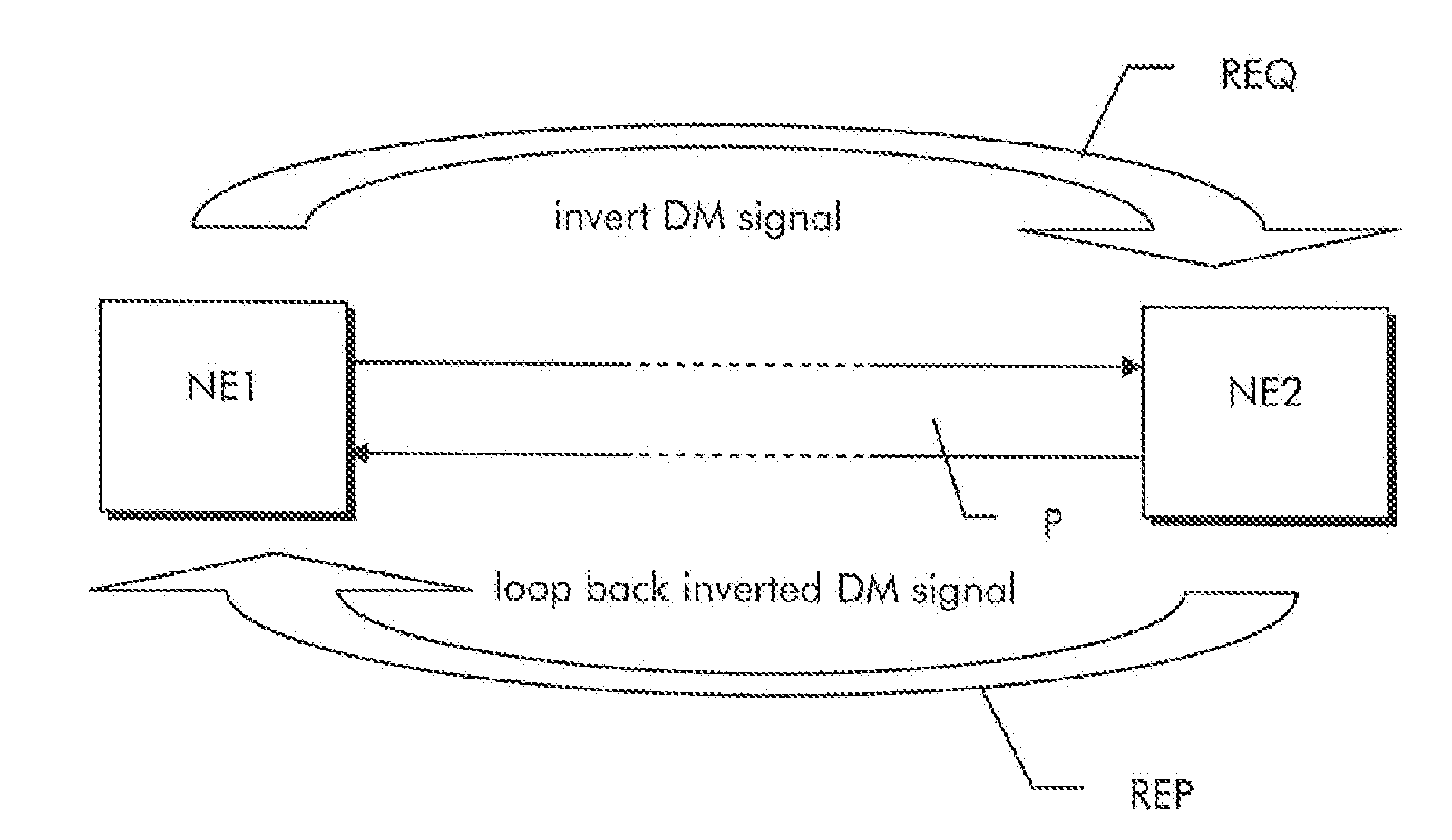
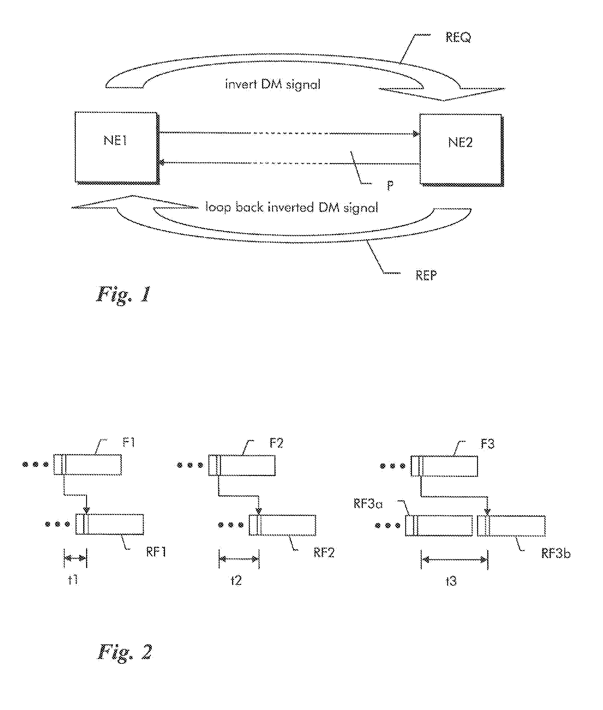
[0014]The principle of a loop back delay measurement is shown schematically in FIG. 1. Two network elements NE1, NE2 are connected over a bidirectional path P. Path P is a sequence of optical links and may lead through a number of intermediate network elements, which are not shown for the sake of simplicity. The path is represented by an optical data unit ODUk. Such optical data units are transported in multiplexed form within a framed transport signal, which contains consecutive transport frames that repeat with a predefined, fixed frame rate. The transport frames are termed Optical Transport Unit of size k (OTUk). The optical data units can be for example an ODU0 that repeats approximately every 100 μsec (more precisely every 98.4 μsec according to ITU-T recommendation G.709, table 7-4).

[0015]Each ODUk has an overhead section which includes a path monitoring (PM) field as described in ITU-T G.709 chapter 15.8.2.1 and FIG. 15-13. The PM field contains a subfield for path delay meas...


PUM


Abstract

A delay measurement method of a path (P) or path segment through a transport network and a corresponding network nodes (NE1, NE2) for performing the delay measurement are described, which provide a higher precision and lower jitter. An originating network node (NE1) inserts a delay measurement request signal (REQ) into an overhead subfield of a first data unit and transmits the first data unit over the path (P) or path segment to a far-end network node (NE2) as part of framed transport signals. The far-end network node (NE2), upon detection of the delay measurement request (REQ), inserts a delay measurement reply signal (REP) into on overhead subfield of a second data unit and transmits the second data unit back to the originating network node (NE1) using framed transport signals in reverse direction. The originating network node (NE1) determines a time difference between insertion of the delay measurement request signal (REQ) and receipt of the delay measurement reply signal (REP). The far-end network node (NE2) further determines an insertion time value indicative of a time difference (t1, t2, t3) between receipt of the delay measurement request signal (REQ) and insertion of the delay measurement reply signal (REP) in reverse direction and communicates the insertion time value back to the originating network node (NE1). The originating network node (NE1) then determines a delay value for the path (P) or path segment from the determined response time difference and the received insertion time value.

Description

FIELD OF THE INVENTION[0001]The invention is based on a priority application EP 11 306 605.4 which is hereby incorporated by reference.[0002]The present invention relates to the field of telecommunications and more particularly to a method and related network element for providing delay measurement in an optical transport network.BACKGROUND OF THE INVENTION[0003]In an optical network, network elements are physically interconnected through optical fiber links. Optical transport signals transmitted over the links are structured into consecutive frames, which repeat with a predefined frame rate.[0004]A connection for the transmission of data signals from end to end through an optical network is referred to as a path and represented by a multiplex unit repeatedly contained in each subsequent frame, such as for example an Optical Data Unit of size k (ODUk) for the Optical Transport Network according to ITU-T G.709. An ODUk has a payload and an overhead portion.[0005]A segment of a path i...

Claims


Application Information

Patent Timeline
Patent Type & Authority Applications(United States)
IPC IPC(8): H04B10/079
CPCH04B10/0795H04J3/0682H04J3/1652
Inventor LOEHR, JUERGENSTURM, WOLFRAM
Owner ALCATEL LUCENT SAS
Learn More