Two pump design with coplanar interface surface

a technology of interface surface and pump, applied in the direction of combination engines, machines/engines, liquid fuel engines, etc., can solve the problems of driving vehicle costs and individual components cos

Active Publication Date: 2014-09-18
GHSP
View PDF6 Cites 21 Cited by
  • Summary
  • Abstract
  • Description
  • Claims
  • Application Information

AI Technical Summary

Benefits of technology

[0004]In one aspect of the present invention, a multi-pump apparatus comprises a first component in a fluid heat transfer system, the first component including a first interface surface, and a pumping component including a second interface surface. The first and second interface surfaces combine to define two pump cavities and a planar interface groove supporting a seal ring that extends around the two pump cavities to prevent leakage of fluid from the pump cavities. The pumping component includes a pump impeller in each of the pump cavities and at least one motor driving the two pump impellers. One or both of the pumping component and the first component also defining a fluid inlet to and a fluid outlet from each of the pump cavities.
[0007]In another aspect of the present invention, a pump apparatus comprises a fluid exchanging component with a fluid reservoir for a fluid transfer system, the fluid exchanging component including a first interface surface, and a pumping component including a second interface surface. The first and second interface surfaces combine to define at least one pump cavity and a planar interface groove supporting a seal ring that extends around the at least one pump cavity to prevent leakage of fluid from the pump cavity. The pumping component includes a pump impeller in the at least one pump cavity and includes at least one motor driving the at least one pump impeller. One or both of the pumping component and the fluid exchanging component also defines a fluid inlet to and a fluid outlet from the at least one pump cavity.
[0008]In another aspect of the present invention, a method of connecting two pumps to a fluid transfer system comprises steps of providing a first component in a fluid heat transfer system, the first component including a first planar interface surface. The method includes providing a pumping component including a second planar interface surface, and attaching the pumping component to the first component with the first and second planar interface surfaces combining to define two pump cavities and a planar interface groove supporting a seal ring that extends around the two pump cavities to prevent leakage of fluid from the pump cavities. The pumping component includes a pump impeller in each of the pump cavities and includes at least one motor driving the two pump impellers. One or both of the pumping component and the first component also define a fluid inlet to and a fluid outlet from each of the pump cavities.
[0009]In another aspect of the present invention, a multi-pump apparatus comprises a first component including a first interface surface, and a pumping component including a second interface surface. The first and second interface surfaces combine to define first and second pump cavities with a planar interface groove therein that supports a continuous-loop seal ring that extends around the first and second pump cavities. When assembled, the seal ring prevents leakage of fluid outside of an area defined by the first and second pump cavities. The pumping component includes first and second pump impellers in the first and second pump cavities, and includes first and second motors driving the first and second pump impellers, respectively. One or both of the pumping component and the first component also define a fluid inlet to and a fluid outlet from the first and second pump cavities. An on-board control circuit board attached to the pumping component is electrically connected to the first and second motors for controlling independent operation of the first and second motors and hence controlling independent operation of the first and second impellers in the first and second cavities, respectively.

Problems solved by technology

Many factors drive vehicle costs, including cost of individual components, secondary processing, subassembly, and assembly to a vehicle.

Method used


Image

  • Two pump design with coplanar interface surface
  • Two pump design with coplanar interface surface
  • Two pump design with coplanar interface surface

Examples


Embodiment Construction

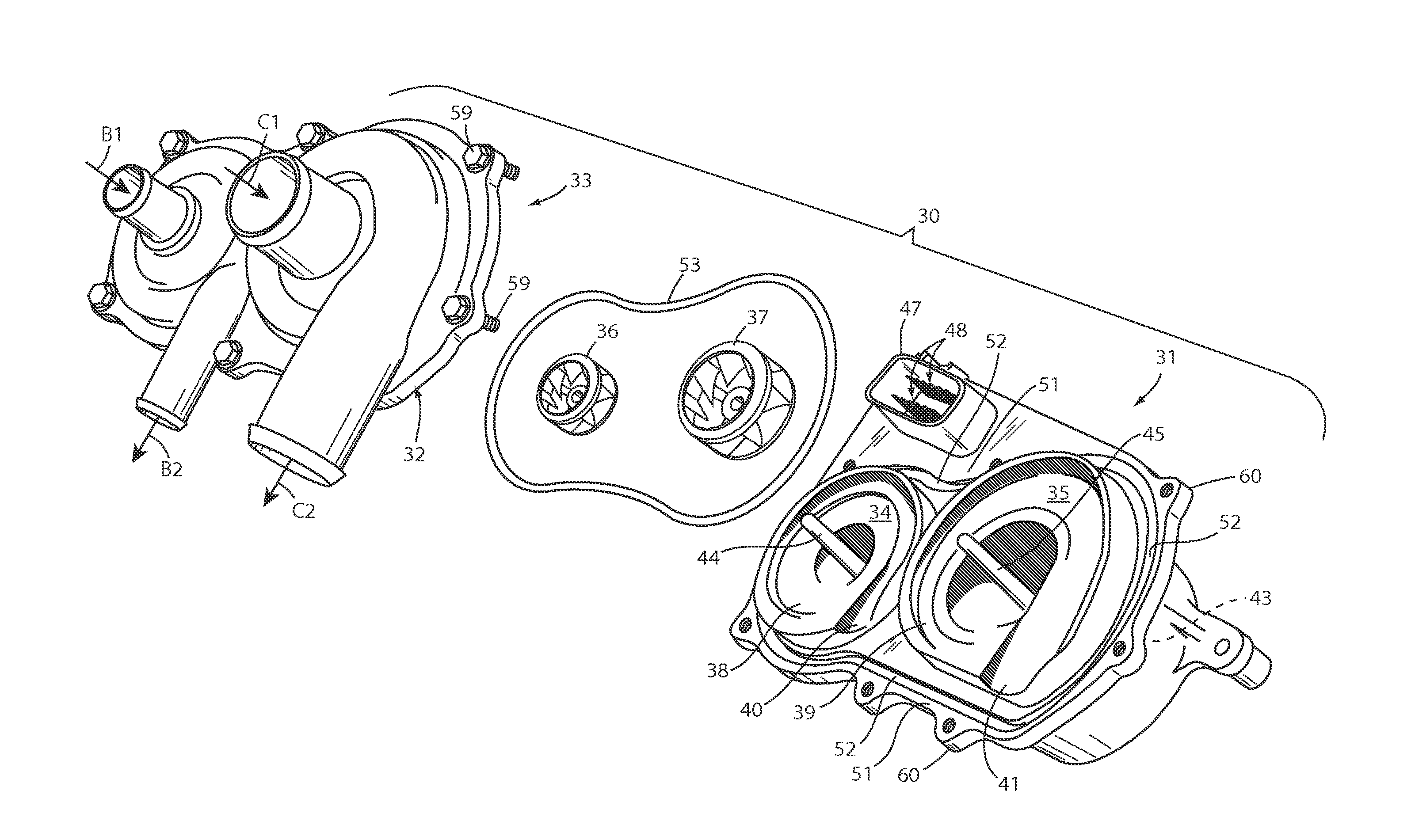
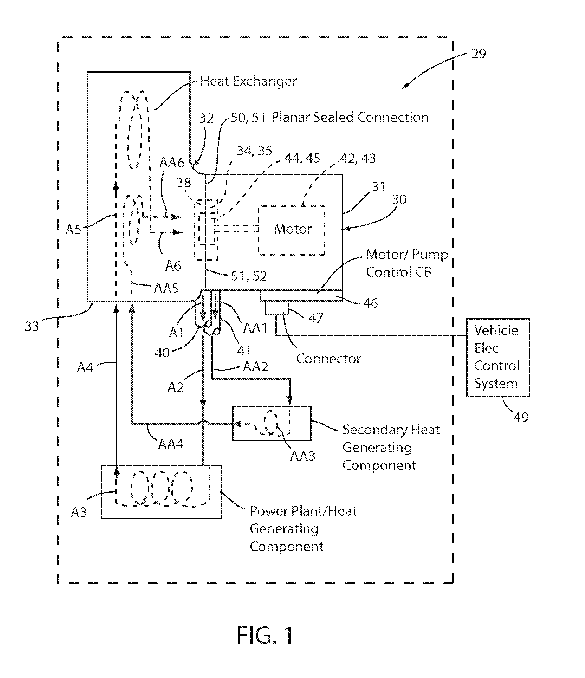
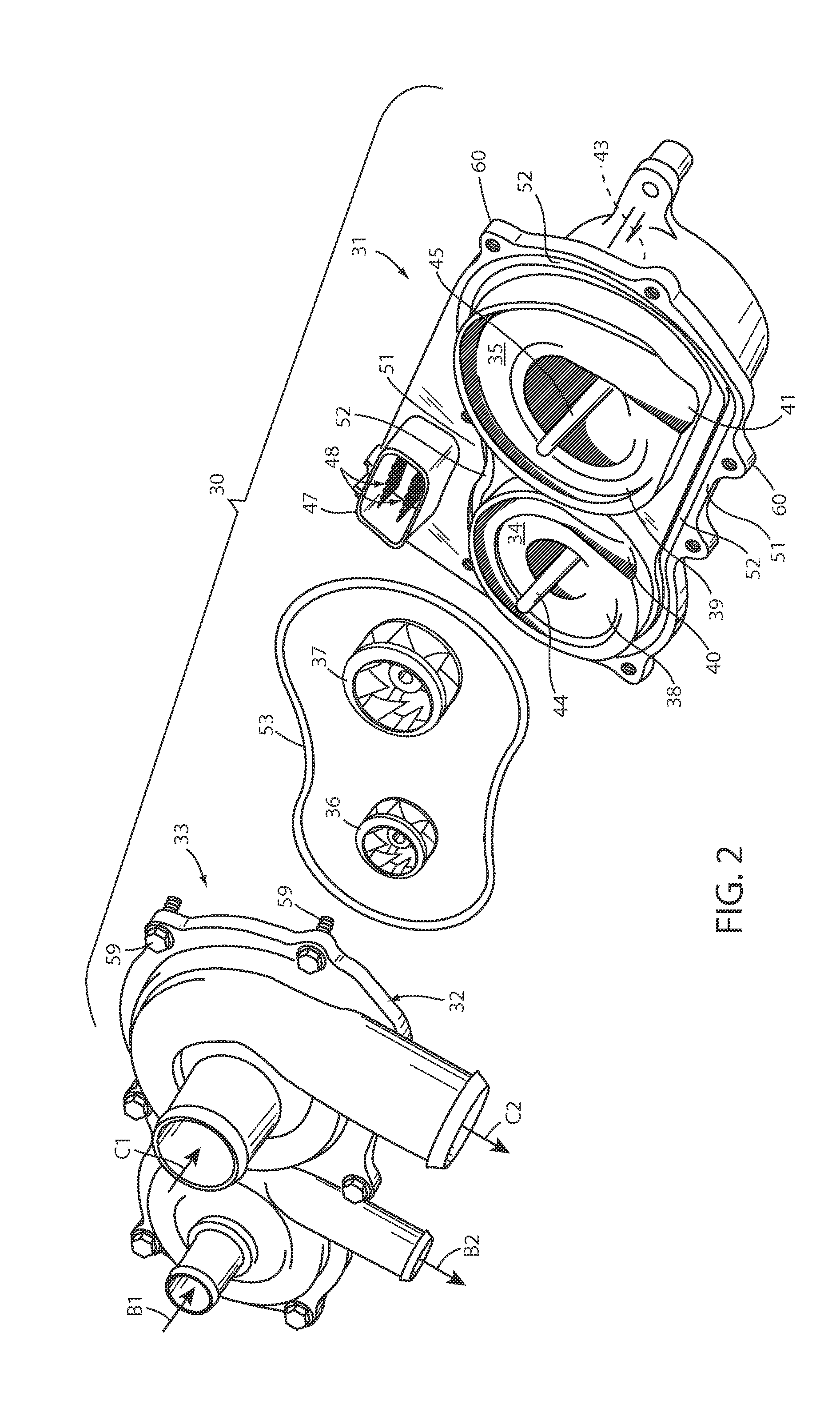
[0014]A dual-pump apparatus 29 (FIG. 1) is designed for use in a fluid heat transfer system. The apparatus 29 includes a multi-pump pumping component 30 (FIGS. 1-4) (two pumps being illustrated) having an integrated housing body 31 (also called a “housing component” herein) configured for abutting sealed attachment to a body portion 32 of a second component 33. The second component 33 can be a component of a fluid heat transfer system, and is illustrated in FIG. 1 as a fluid reservoir or heat exchanger component (e.g. a molded end of a vehicle radiator). For example, it is contemplated that the laterally-extending wall forming the attachment flanges (see attachment fasteners 59 in FIG. 2) can be an integral part of a wall of the heat exchanger component, as discussed below. A combination of the housing body 31 and body portion 32 form two pump cavities 34 and 35 on the second component 33. The pumping component 30 includes two pump impellers 36 and 37 positioned in the pump cavities...


PUM

PropertyMeasurementUnit
areaaaaaaaaaaa
dimensionsaaaaaaaaaa
sizeaaaaaaaaaa

Abstract

A multi-pump apparatus includes a first component in a fluid heat transfer system, such as a heat exchanger, the first component including a body portion forming a first interface surface. A pumping component includes a second interface surface. The first and second interface surfaces are planar and combine to define two pump cavities and a planar interface groove supporting a seal ring that extends around the two pump cavities to prevent leakage of fluid from the pump cavities. The pumping component includes a pump impeller in each of the pump cavities and independently-controlled separate motors driving the two pump impellers using an on-board circuit board. One of the first and second components also defines a fluid inlet to and a fluid outlet from each of the pump cavities. Related methods are also defined.

Description

CROSS-REFERENCE TO RELATED APPLICATION[0001]This application claims priority to Provisional Patent Application Ser. No. 61 / 778,721, filed on Mar. 13, 2013, entitled TWO PUMP DESIGN WITH COPLANAR INTERFACE SURFACE, the entire disclosure of which is hereby incorporated by reference in its entirety.BACKGROUND OF THE INVENTION[0002]The present invention relates to a pump apparatus including a pumping component with two pump cavities formed by mating bodies of the pump apparatus and a component in a fluid transfer system, such as a reservoir or radiator or heat exchanger. The pump apparatus may be used to controllably cool a power generating system of a vehicle along with a secondary heat generating system on the vehicle.[0003]Many factors drive vehicle costs, including cost of individual components, secondary processing, subassembly, and assembly to a vehicle. It is desirable to provide an improved pump design with reduced number of components, reduced cost of manufacturing components, ...

Claims


Application Information

Patent Timeline
Patent Type & Authority Applications(United States)
IPC IPC(8): F04D29/40
CPCF04D29/406F04D13/14Y10T29/49236F04D29/426
Inventor ROSINSKI, RYAN
Owner GHSP
Why Eureka
Try Eureka