Inserting inhibitor to create part boundary isolation during 3D printing

a 3d printing and inhibitor technology, applied in the field of printers, can solve the problems of difficult separation of adjacent, uninhibited powder regions after they are sintered, and achieve the effect of preventing the formation of uninhibited powder regions

Active Publication Date: 2014-09-18
UNIV OF SOUTHERN CALIFORNIA
View PDF12 Cites 126 Cited by
  • Summary
  • Abstract
  • Description
  • Claims
  • Application Information

AI Technical Summary

Benefits of technology

[0019]Guy wires may be attached to the nozzle that prevent the nozzle from bending while the nozzle is moved inside the base powder and inhibitor material is being inserted.

Problems solved by technology

Although SIS technology can be used to fabricate polymeric and metallic parts, in cases of very high temperature sintering it can be difficult to separate adjacent, uninhibited powder regions after they are sintered.

Method used


Image

  • Inserting inhibitor to create part boundary isolation during 3D printing
  • Inserting inhibitor to create part boundary isolation during 3D printing
  • Inserting inhibitor to create part boundary isolation during 3D printing

Examples


Embodiment Construction

[0033]Illustrative embodiments are now described. Other embodiments may be used in addition or instead. Details that may be apparent or unnecessary may be omitted to save space or for a more effective presentation. Some embodiments may be practiced with additional components or steps and / or without all of the components or steps that are described.

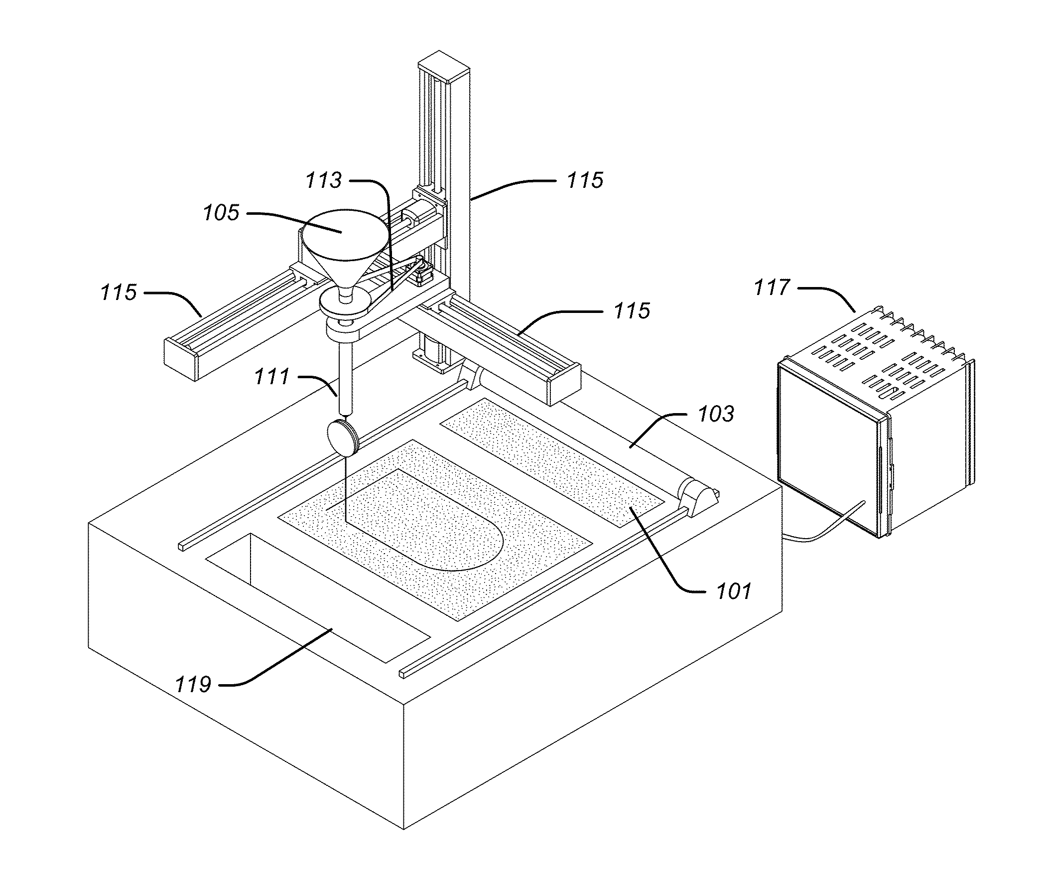
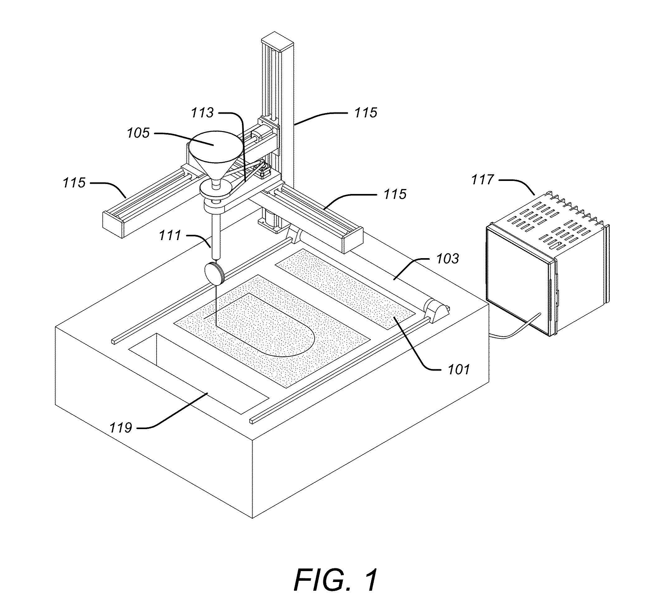
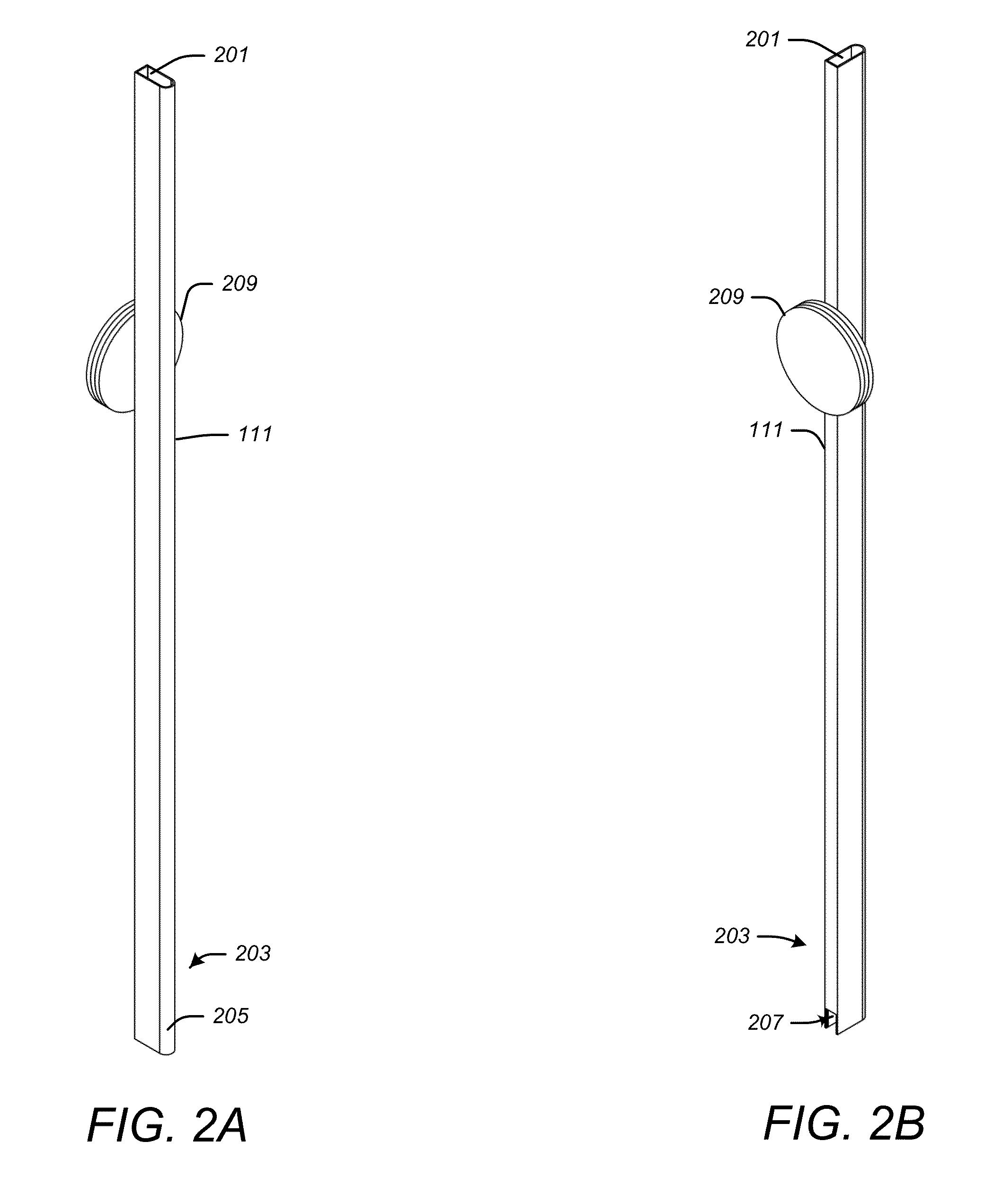
[0034]FIG. 1 illustrates an example of a 3D printing system that creates part boundary isolation during 3D printing by inserting inhibitor material. The 3D printing system may include fusible powder 101 that fuses when subjected to a fusing condition; a deposition system that may include a powder spreading roller 103 that deposits portions of the fusible powder in form of a thin layer; a fusing system (not shown) that applies the fusing condition to the deposited fusible powder; inhibitor material 105 that may be in a hopper and that does not fuse when subjected to the fusing condition; and an insertion system that inserts a portion of the...


PUM

PropertyMeasurementUnit
shapeaaaaaaaaaa
forceaaaaaaaaaa
gravityaaaaaaaaaa

Abstract

A 3D printing system may print a desired 3D object. A fusible powder may fuse when subjected to a fusing condition. A deposition system may deposit portions of the fusible powder on a substrate. A fusing system may apply the fusing condition to the deposited fusible powder. Inhibitor material may not fuse when subjected to the fusing condition. An insertion system may insert a portion of the inhibitor material between portions of the deposited fusible powder after having been deposited by the deposition system, but before being fused by the fusing system, so as to form a boundary that defines at least a portion of a surface of the desired 3D object.

Description

CROSS-REFERENCE TO RELATED APPLICATION[0001]This application is based upon and claims priority to U.S. provisional patent application 61 / 777,939, entitled “3D PRINTING BY PART BOUNDARY ISOLATION THROUGH POWDER PARTICLE INSERTION,” filed Mar. 12, 2013, attorney docket number 028080-0852. The entire content of this application is incorporated herein by reference.BACKGROUND[0002]1. Technical Field[0003]This disclosure relates to printers that produce desired three-dimensional (3D) objects by fusing deposited powder, including 3D printers that use selective inhibition sintering (SIS).[0004]2. Description of Related Art[0005]Selective inhibition sintering (SIS) may be used to fabricate meso-scale polymeric and metallic parts. The fabrication may be in layers using loose powder as the initial material. Polymeric or metallic powder may be printed in thin layers. After each layer is printed, a liquid may be inkjet-printed on the layer in a pattern that defines the periphery of that layer, t...

Claims


Application Information

Patent Timeline
Patent Type & Authority Applications(United States)
IPC IPC(8): B22F3/00C04B35/622
CPCC04B35/622B22F3/003C04B35/634C04B2235/6026B29L2023/00B29C64/153B29C64/165Y02P10/25B22F12/53B22F10/14B33Y30/00B22F2003/1032B22F2003/1054B28B1/001C04B33/04C04B33/24C04B35/48C04B35/62218C04B35/6303C04B35/63452
Inventor KHOSHNEVIS, BEHROKH
Owner UNIV OF SOUTHERN CALIFORNIA
Why Eureka
Try Eureka