
Decision support tool for use with a medical monitor-defibrillator

a technology of defibrillator and decision support, which is applied in the field of external defibrillators, can solve the problems of irregular heart beating, and not at all, and reducing the amount of blood pumped to the various parts of the body

Active Publication Date: 2014-09-18
PHYSIO CONTROL INC
View PDF13 Cites 25 Cited by
  • Summary
  • Abstract
  • Description
  • Claims
  • Application Information

AI Technical Summary

Benefits of technology

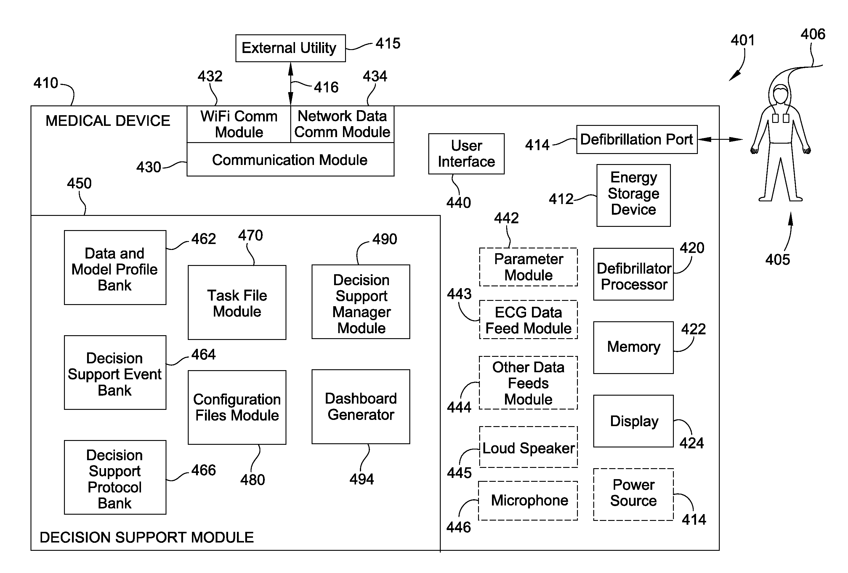
The present patent describes devices, systems, software and methods for overcoming problems and limitations of the prior art. It uses a modeling system to create a visual representation of tasks to be performed, which can be easily interacted with. The system allows for the creation of decision support files and protocols for use in a defibrillation procedure. Overall, the technology helps streamline the decision-making process and improves the efficiency of medical procedures.

Problems solved by technology

Sometimes, however, the electrical control system of the heart malfunctions, which can cause the heart to beat irregularly, or not at all.
Some types of arrhythmia may result in inadequate blood flow, thus reducing the amount of blood pumped to the various parts of the body.
In an SCA, the heart fails to pump blood effectively, and, if not corrected, can result in death.
It is estimated that SCA results in more than 250,000 deaths per year in the United States alone.
When that happens, the heart does not pump enough blood to deliver enough oxygen to the vital organs.
The person's condition will deteriorate rapidly and, if not corrected in time, will result in death, e.g. within ten minutes.
A challenge with defibrillation is that the electrical shock must be administered very soon after the onset of VF.
Regardless, VF can occur unpredictably, even to a person who is not considered at risk.

Method used


Image

  • Decision support tool for use with a medical monitor-defibrillator
  • Decision support tool for use with a medical monitor-defibrillator
  • Decision support tool for use with a medical monitor-defibrillator

Examples


Embodiment Construction

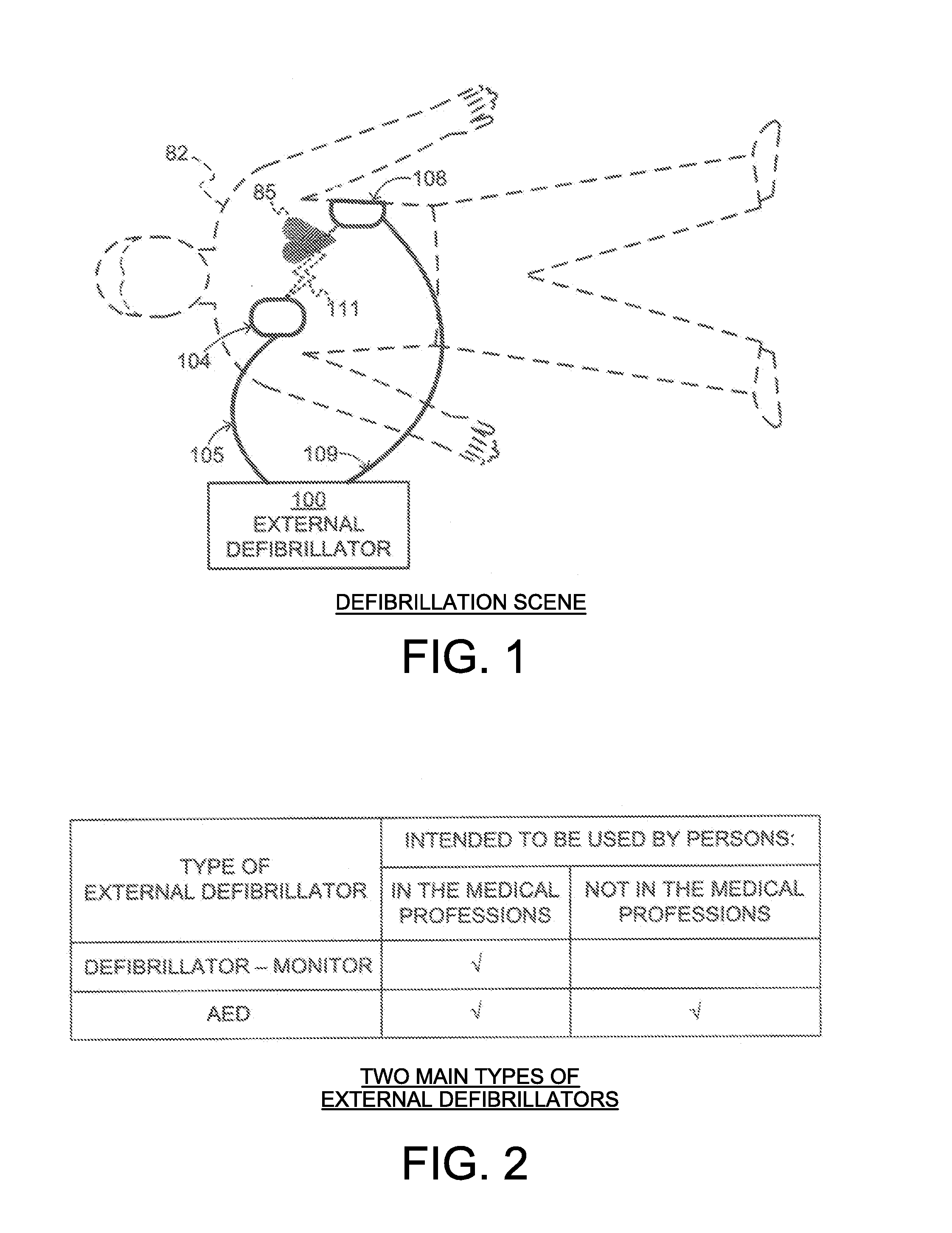
[0032]FIG. 1 is a diagram of a defibrillation scene showing the use of an external defibrillator to save the life of a person according to this disclosure. As shown, a person 82 is lying on his back. Person 82 could be a patient in a hospital, or someone found unconscious, and then turned over onto his back. Person 82 is experiencing a condition in their heart 85, which could be Ventricular Fibrillation (VF).

[0033]A portable external defibrillator 100 has been brought close to person 82. At least two defibrillation electrodes 104, 108 are typically provided with external defibrillator 100, and are sometimes called electrodes 104, 108. Electrodes 104, 108 are coupled together with external defibrillator 100 via respective electrode leads 105, 109. A rescuer (not shown) has attached electrodes 104, 108 to the skin of person 82. Defibrillator 100 is administering, via electrodes 104, 108, a brief, strong electric pulse 111 through the body of person 82. Pulse 111, also known as a defib...


PUM


Abstract

Work flows are modeled as a graph of interdependent tasks to be performed. The tasks to be performed are set by a task file module configured to enable interactions between tasks and including modules for event viewing, protocol assistance, smart messaging, smart indices, reference material lookup. A decision support manager module is configured to construct data and model profiles for storage in a data and model profile bank, events for storage in a decision support events bank, and protocols for storage in a decision support protocol bank. Configuration files are provided to specify a configuration for execution of one of the tasks. Data entered through a user interface or from a network via a wireless or wired communication module may define task files in the task files module, configuration files in the configuration files module, as well as data, events, and protocols to be used for a defibrillation procedure. A decision support manager module is configured to construct a dependency graph of tasks as specified in at least one of the configuration files and to execute the dependency graph.

Description

CROSS REFERENCE TO RELATED PATENT APPLICATIONS[0001]This patent application may be found to be related to U.S. patent application Ser. No. ______, entitled “Clinical Dashboard for Medical Device”, filed contemporaneously herewith in the name of Randy L. Merry et al.; and U.S. patent application Ser. No. ______, entitled “Medical Monitor-Defibrillator with Defibrillator and Data Operations Processors”, filed contemporaneously herewith in the name of Ken Peterson et al.FIELD[0002]This invention generally relates to external defibrillators.BACKGROUND[0003]In humans, the heart beats to sustain life. In normal operation, it pumps blood through the various parts of the body. More particularly, the various chamber of the heart contract and expand in a periodic and coordinated fashion, which causes the blood to be pumped regularly. More specifically, the right atrium sends deoxygenated blood into the right ventricle. The right ventricle pumps the blood to the lungs, where it becomes oxygena...

Claims


Application Information

Patent Timeline
Patent Type & Authority Applications(United States)
IPC IPC(8): G06F19/00A61B5/00
CPCA61B5/002G06F19/345A61B5/7282A61B5/02055A61B5/021A61B5/0836A61B5/14551A61B5/4836A61N1/3993G16H50/20A61B5/318A61B5/33
Inventor PETERSON, KENSMITH, MITCHELL A.EDWARDS, DENNY CRAIGBARCELOS, NATHANIEL PAULWOOTTEN, JAMESYOUNG, CLAYTONMERRY, RANDY L.LEWIS, DANA S.DAYNES, JOHN C.JUHASZ, PAUL R.OKEY, DAVIDWITTERS, STEVENTURNER, IRA M.
Owner PHYSIO CONTROL INC
Learn More