
Tracking device and remote monitoring system

a tracking device and monitoring system technology, applied in the direction of electrical equipment, location information based services, wireless communication, etc., can solve the problems of device not exploiting the variety of network signals, not exploiting network knowledge, etc., and achieve the effect of relieving anxieties

Inactive Publication Date: 2014-09-18
GRID ROOTS
View PDF5 Cites 51 Cited by
  • Summary
  • Abstract
  • Description
  • Claims
  • Application Information

AI Technical Summary

Benefits of technology

This patent describes a device that combines a network of networks to help locate and communicate with other parts of a grid. The device can use map technology and personal computers to help parents quickly find their child, or monitor the location of children with cognitive disabilities. The device can also be used to improve security for the elderly and handicapped, as well as to collect statistics on wait times at attractions. The ultimate goal is to provide more safety and comfort for parents and allow caregivers to better understand where their loved ones are located.

Problems solved by technology

These devices do not exploit the variety of network signals, such as GPS, Cellular, Bluetooth, Wi-Fi and others that are available for determining position.
Further, they do not exploit knowledge about the networks and the environments the tracking devices are operating in to aid in refining their knowledge of position.

Method used


Image

  • Tracking device and remote monitoring system
  • Tracking device and remote monitoring system
  • Tracking device and remote monitoring system

Examples


Embodiment Construction

[0022]In the following detailed description, numerous specific details are set forth in order to provide a thorough understanding of the embodiments of the present invention. It will be understood by those of ordinary skill in the art that these embodiments of the present invention may be practiced without some of these specific details. In other instances, well-known methods, procedures, components and structures may not have been described in detail so as not to obscure the embodiments of the present invention.

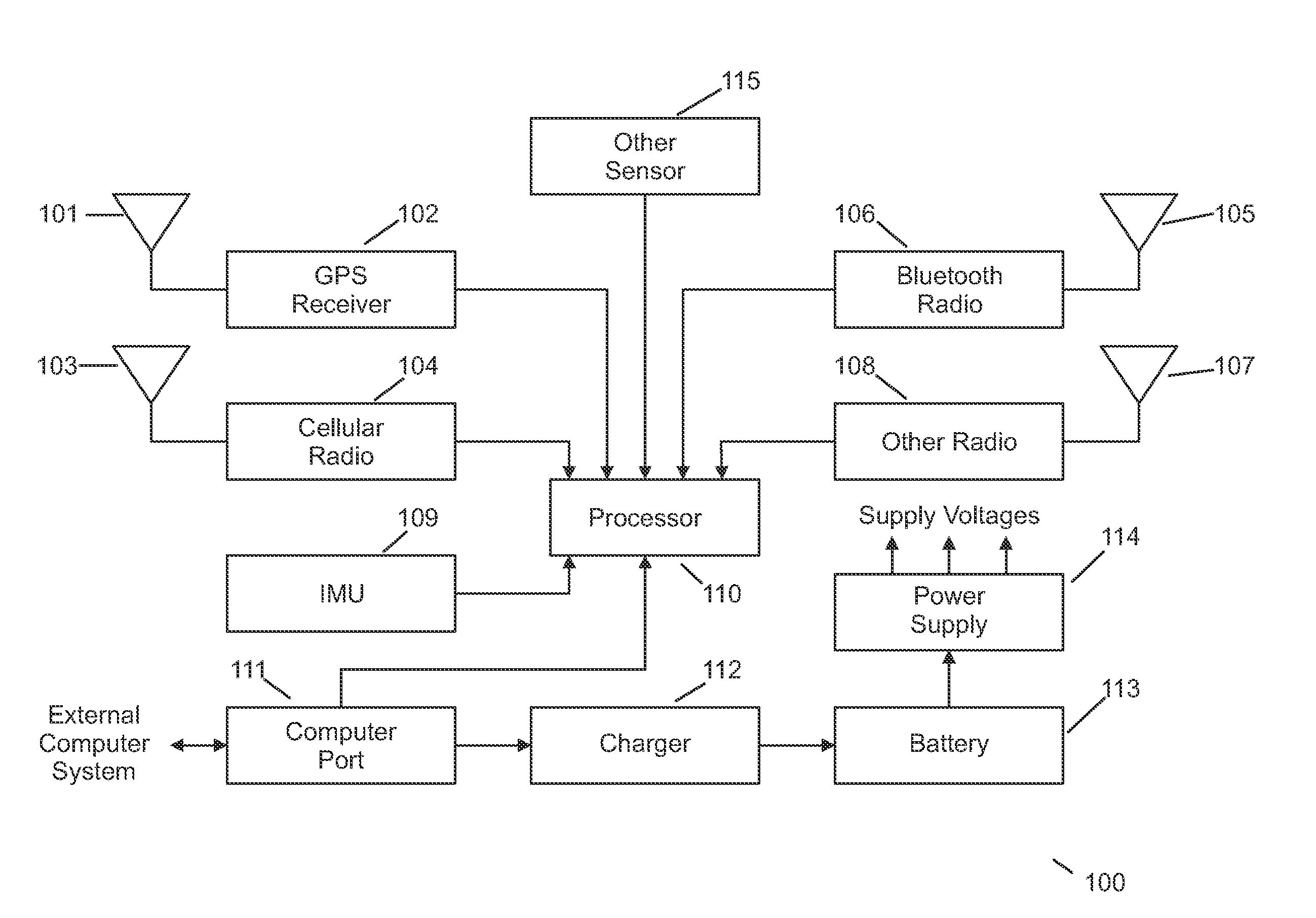
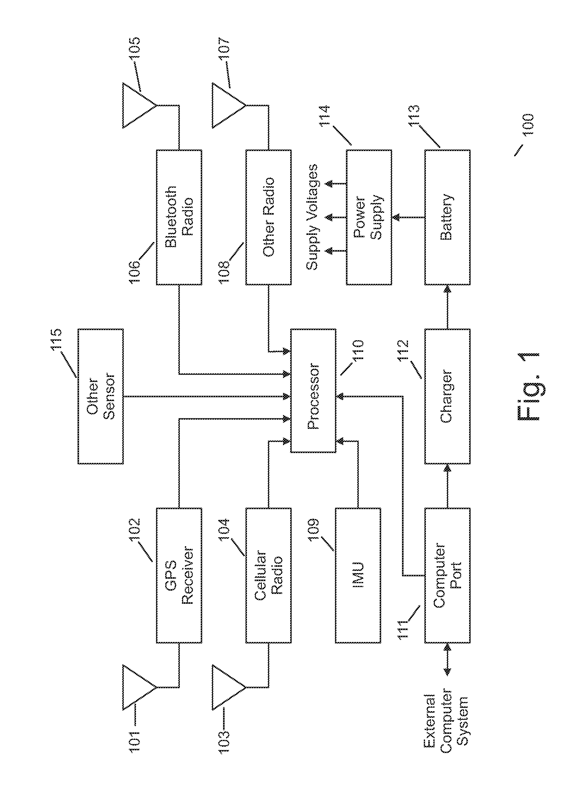
[0023]Referring to FIG. 1, the remote monitoring device (RMD) 100 is the portion of the system that is attached to, or otherwise carried by, the person or asset that is being tracked and / or monitored. In one embodiment, remote monitoring device 100 contains a position determining device, such as GPS receiver 102, or the like, which yields an absolute position such as a latitude and longitude; a Cellular radio 104 which allows for computing position using techniques known in ...


PUM


Abstract

A system includes a remote monitoring device configured to detect and measure one or more signals and to convey detected and measured signal information to a central location. The central location is configured to determine the location of the remote monitoring device based on the received signal information and is also configured to determine at least one hypothetical path of the remote monitoring device.

Description

BACKGROUND OF THE INVENTION[0001]During the past several years there has been unprecedented growth in applications of location technologies such as the Global Positioning System (GPS), Assisted-GPS (AGPS), Cellular Radio-based location determination and others. Location determination is typically performed using known techniques such as measuring the time of arrival (TOA) of radio signals between source and destination, using time-difference of arrival (TDOA), angle of arrival (AOA), received signal strength indicators (RSSI) or some combination of these measurements to estimate the range and / or bearing between the source(s) and destination(s) of a radio signal. Using these estimates of range and / or, it is then possible to use known techniques such as triangulation, multilateration, trilateration and such to determine the absolute location of a device relative to some desired coordinate system (for example, latitude and longitude). While the coordinate system used is arbitrary, for ...

Claims


Application Information

Patent Timeline
Patent Type & Authority Applications(United States)
IPC IPC(8): H04W4/02H04W4/029
CPCH04W4/028H04W4/029
Inventor MICHALSON, WILLIAM R.KOLM, LUKASTRAYNER, JOHN R.DESROCHES, RYAN J.
Owner GRID ROOTS
Learn More