Endoprosthesis delivery systems with deployment aids

a technology of endoprosthesis and delivery system, applied in the field of endoprosthesis, can solve problems such as preventing the bunching of the cover

Active Publication Date: 2014-09-18
WL GORE & ASSOC INC
View PDF7 Cites 9 Cited by
  • Summary
  • Abstract
  • Description
  • Claims
  • Application Information

AI Technical Summary

Benefits of technology

[0003]The present disclosure includes an endoprosthesis delivery system comprising an elongate member, such as a catheter, an endoprosthesis, a covering member disposed about the endoprosthesis, and at least one flexible element situated between the endoprosthesis and the covering member. The covering member can extend beyond an end of the endoprosthesis. In operation, as the covering member is removed, the flexible element can guide the covering member over the end of the endoprosthesis to prevent entanglement between the end of the endoprosthesis and the covering member.
[0004]The present disclosure further includes an endoprosthesis delivery system comprising an elongate member having a slip resistant section or material, an endoprosthesis, and a covering member. The slip resistant material can comprise a gummy or mildly sticky material or a compressible material as described, and it can extend beyond a distal and / or proximal end of the endoprosthesis. In operation, as the covering member unravels or is otherwise removed to release the endoprosthesis, the slip resistant material can impede bunching of the cover. This can, in turn, prevent, or help to prevent, entanglement between the covering member and the endoprosthesis.

Problems solved by technology

In operation, as the covering member unravels or is otherwise removed to release the endoprosthesis, the slip resistant material can impede bunching of the cover.

Method used


Image

  • Endoprosthesis delivery systems with deployment aids
  • Endoprosthesis delivery systems with deployment aids
  • Endoprosthesis delivery systems with deployment aids

Examples


example 1

Delivery System Construction

[0095]In various embodiments, an endoprosthesis delivery system 100 can be manufactured and / or constructed as follows. Generally, an inner shaft 102 wrapping procedure can be followed by an endoprosthesis loading procedure. The inner shaft 102 wrapping procedure can begin with the insertion of a processing mandrel and / or an appropriate inner shaft 102 within a pair of processing chucks coupled to a film wrapping device. The wrapping device can comprise a film payoff head, which can be configured to travel along a length of the inner shaft 102 to wrap a tape or other compressible or compliant material, as described herein, about the shaft 102. Thus, the inner shaft 102 can be wrapped with a compliant material by the wrapping device. In various embodiments, the film payoff head can make a first pass along an axial length of the shaft 102 and a second pass, in the reverse direction, along the shaft 102 as well. However, the film payoff head can, in other emb...

example 2

Delivery System Construction

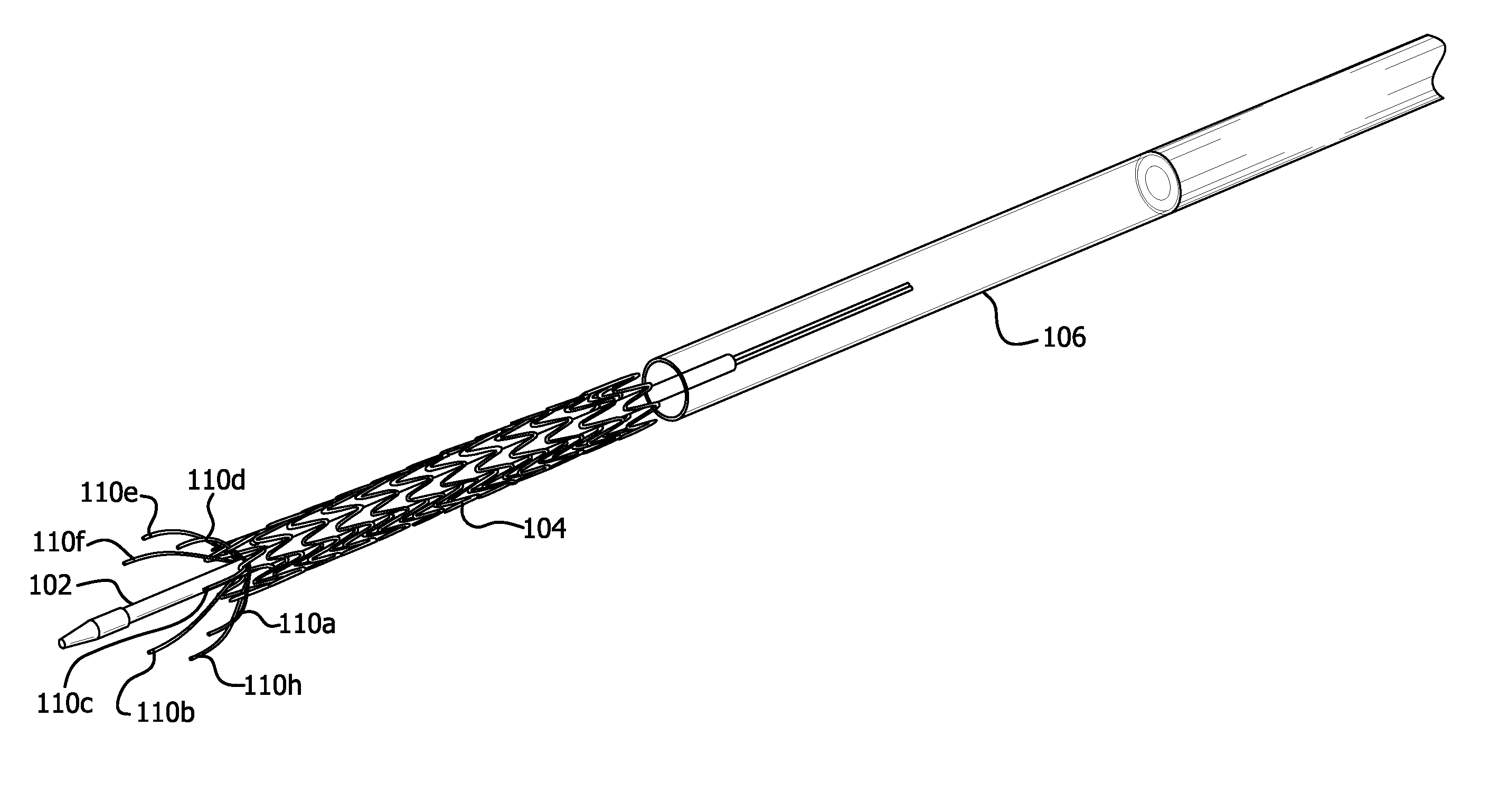
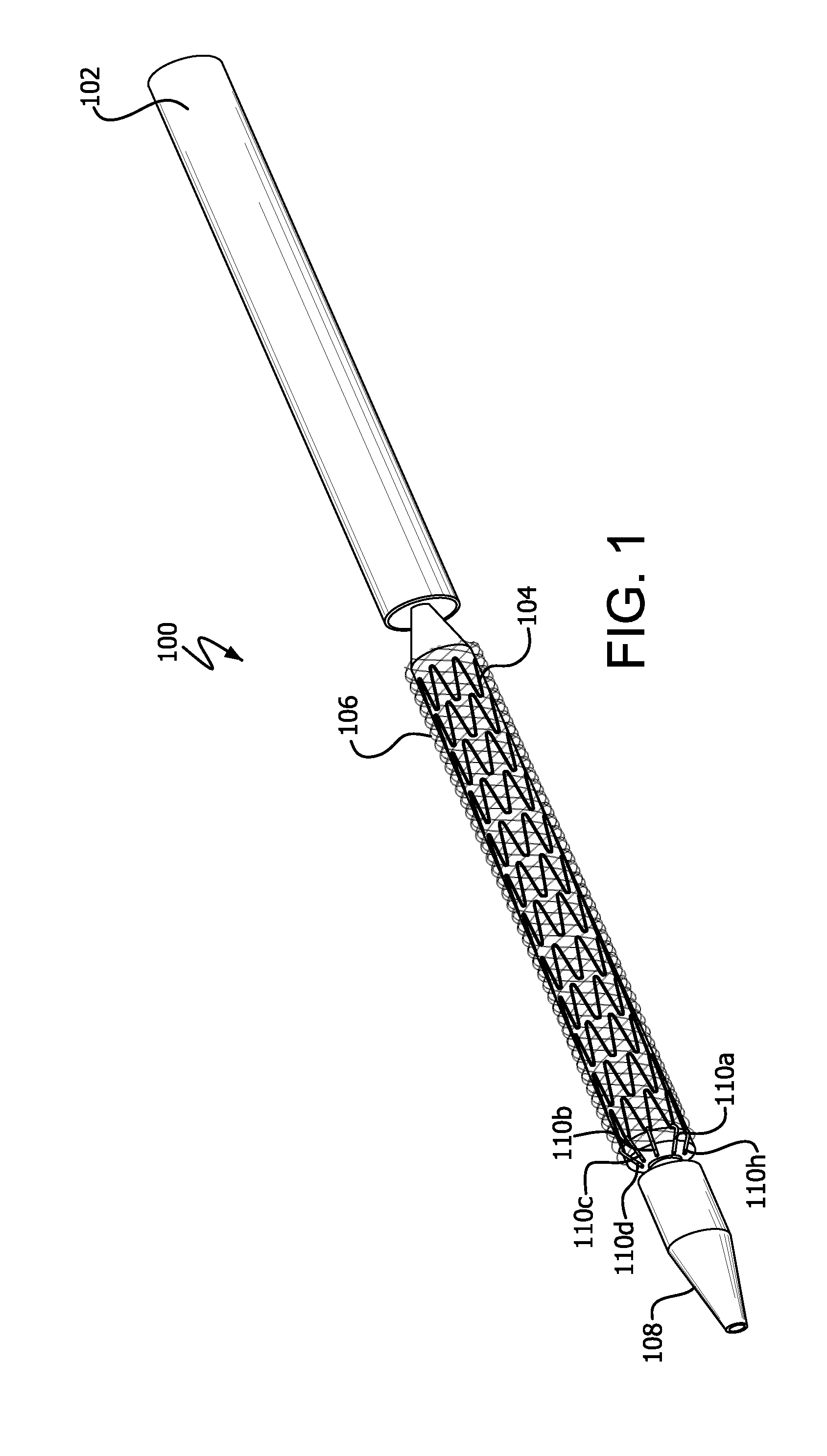
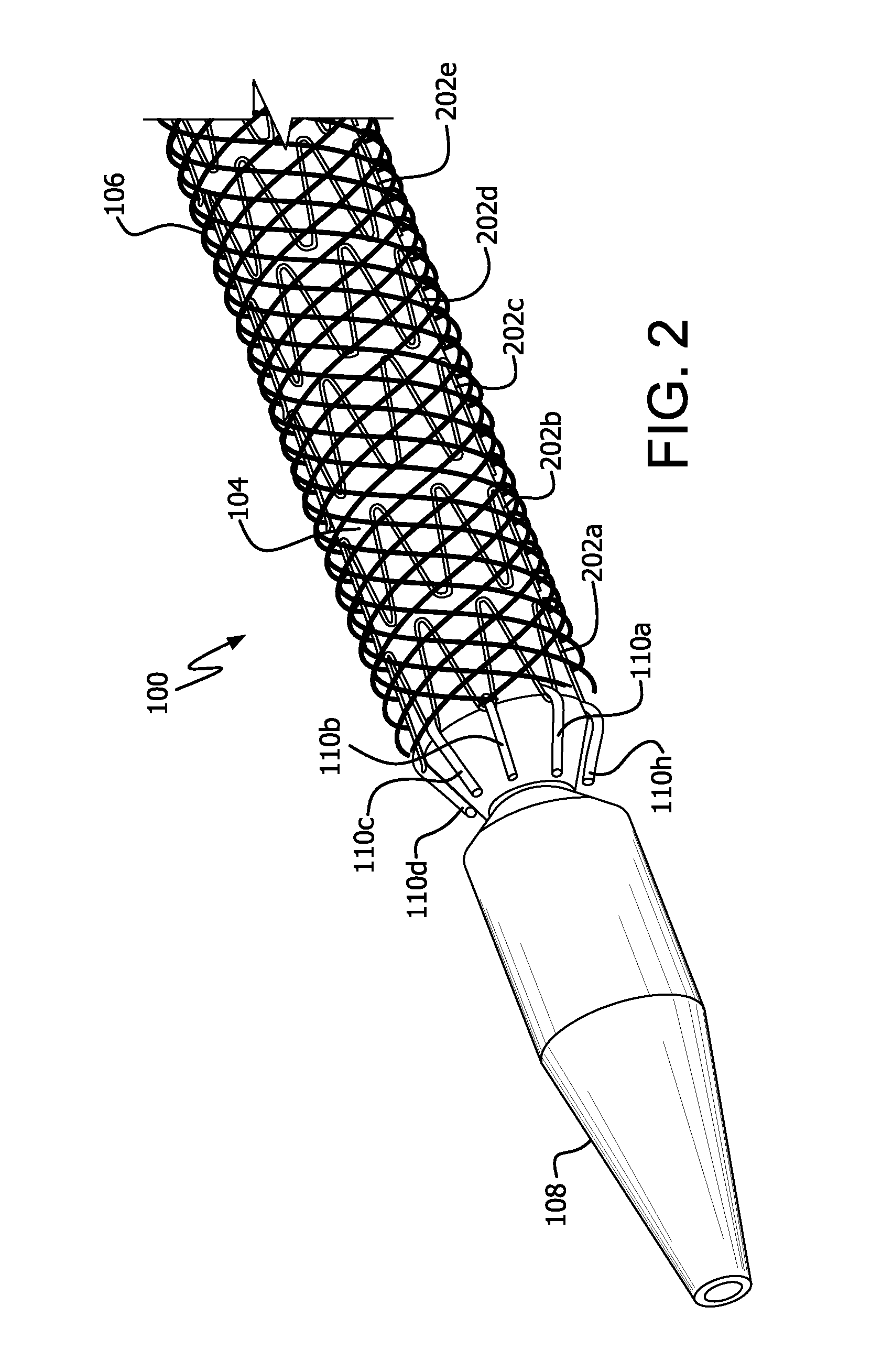
[0098]Continuing, in various embodiments, an endoprosthesis delivery system can be constructed and / or manufactured with an end cap 1402 and / or a tapered end cap 1406 as follows. An endoprosthesis 104 can, as described herein, be loaded through a loading funnel. A process for loading an endoprosthesis through a loading funnel is also generally described by U.S. Pat. No. 6,702,845 to Cully et al., issued Mar. 9, 2004, entitled “Compacted implantable medical devices and method of compacting such devices” which is hereby incorporated by reference in its entirety. The endoprosthesis 104 can be loaded by insertion through the loading funnel on the inner shaft 102. The distal end of the endoprosthesis can pass through the funnel last, so that the proximal end of the endoprosthesis 104 is received, at the smaller diameter end of the funnel, and as described above, by the covering member 106.

[0099]At the distal end of the endoprosthesis 104, the end cap 1402 can b...

example 3

Delivery System Construction

[0101]In various embodiments, a small tubular extrusion of PEBAX can be obtained. The extrusion dimensions can be approximately 1 mm ID×1.2 mm OD, and the material can have a Shore A hardness of 55. A stainless steel mandrel can be inserted into the extrusion lumen and gripped at both ends in a fixture to allow rotation of the extrusion. Further, an ePTFE film, as disclosed by U.S. Pat. No. 5,814,405 to BRANCA, et al., issued Sep. 29, 1998, entitled “Strong, air permeable membranes of polytetrafluoroethylene,” which is hereby incorporated by reference in its entirety, can be wrapped about the extruded tube and attached to the extrusion through thermal treatment, for example using a Weller soldering iron. A strip of film (e.g., in various embodiments, a strip of approximately 80 mm in width) can be longitudinally wrapped about the extrusion parallel to the central axis of the extrusion, using minimal tension, by rotating the extrusion. Where such a strip i...


PUM

PropertyMeasurementUnit
widthaaaaaaaaaa
lengthaaaaaaaaaa
flexibleaaaaaaaaaa

Abstract

The present disclosure includes an endoprosthesis delivery system comprising an elongate member, such as a catheter, an endoprosthesis, a covering member disposed about the endoprosthesis, and at least one flexible element situated between the endoprosthesis and the covering member. The covering member can extend beyond an end of the endoprosthesis. In operation, as the covering member is removed, the flexible element can guide the covering member over the end of the endoprosthesis to prevent entanglement between the end of the endoprosthesis and the covering member.

Description

FIELD[0001]The present disclosure generally relates to endoprostheses for treating diseases of the vasculature and similar anatomies, and more particularly to endoprosthesis delivery systems for preventing entanglement of covering members with such endoprostheses.BACKGROUND[0002]Many endoprostheses (or endoprosthetic devices), such as, for example, stent-grafts, are constructed to reinforce, replace, bridge, or otherwise treat a part of a blood vessel. An endoprosthesis may thus guide blood flow through a lumen defined by a generally tubular interior of such a vessel. Other tubular endoprostheses are designed for use in other body regions, for example, the esophagus, ureters, gastrointestinal tract and various ducts. In many cases, endoprostheses are constrained within a covering member or sheath, and when the covering member is removed, as during deployment, the devices expand, are expanded under force or self-expand to assume a larger diameter. From time to time, however, as a cov...

Claims


Application Information

Patent Timeline
Patent Type & Authority Applications(United States)
IPC IPC(8): A61F2/958A61F2/06A61F2/07A61F2/82A61F2/966
CPCA61F2/958A61F2002/9665A61F2/97A61F2/07Y10T29/49826A61F2/962A61F2/966
Inventor ARMSTRONG, JOSEPH R.CULLY, EDWARD H.DUNCAN, JEFFREY B.KOVACH, LARRY J.PAJOT, DOUGLAS F.SHORT, BRANDON C.ULM, MARK J.VONESH, MICHAEL J.
Owner WL GORE & ASSOC INC
Why Eureka
Try Eureka