Oblique stent

a stent and oblique technology, applied in the field of stents, can solve the problems of metal overlap, collision and stent strut distortion, and reduce the acute and late (long-term) chances of procedural success,

Active Publication Date: 2014-09-18
CURAVAS GMBH
View PDF2 Cites 11 Cited by
  • Summary
  • Abstract
  • Description
  • Claims
  • Application Information

AI Technical Summary

Benefits of technology

[0015]In accordance with further features in embodiments of the invention, the stent wall may have a bottom portion having a first strut configuration and a top portion having a second strut configuration. In some embodiments, the bottom portion includes a longitudinal contracting strut configuration having a bottom portion first length in an unexpanded state and a bottom portion second length upon expansion of the tubular stent, wherein the bottom portion second length is shorter than the bottom portion first length due to the longitudinal contracting strut configuration, and wherein the top portion includes a longitudinal length-maintaining strut configuration, wherein the top portion has a top portion first length in an unexpanded state and a top portion second length upon expansion of the tubular stent, wherein the top portion second length is substantially the same as the top portion first length due to the longitudinal length-maintaining strut configuration.
[0016]Unless otherwise defined, all technical and scientific terms used herein have the same meaning as commonly understood by one of ordinary skill in the art to which this invention belongs. Although methods and materials similar or equivalent to those described herein can be used in the practice or testing of the embodiments of the present invention, suitable methods and materials are described below. In case of conflict, the patent specification, including definitions, will control. In addition, the materials, methods, and examples are illustrative only and not intended to be limiting.

Problems solved by technology

Conventional stents may not adequately provide coverage in such circumstances.
Moreover, if two stents are needed for treatment of a lesion in the main branch, with the necessity of bridging the ostium of the side branch, the protruding portions of the stents may lead to metal overlap, collision and stent strut distortion.
This may reduce the acute and late (long term) chances of procedural success, as well as lead to immediate complications, such as an increased risk for thrombosis in the stents.
However, Ischinger does not disclose a specific design of an oblique stent which can be used to meet the requirements of successful bifurcation stent treatment.

Method used


Image

  • Oblique stent
  • Oblique stent
  • Oblique stent

Examples


Embodiment Construction

[0032]In the following detailed description, numerous specific details are set forth in order to provide a thorough understanding of the present invention. It will be understood by those of ordinary skill in the art that embodiments of the present invention may be practiced without these specific details. In other instances, well-known methods, procedures, components and structures may not have been described in detail so as not to obscure the present invention.

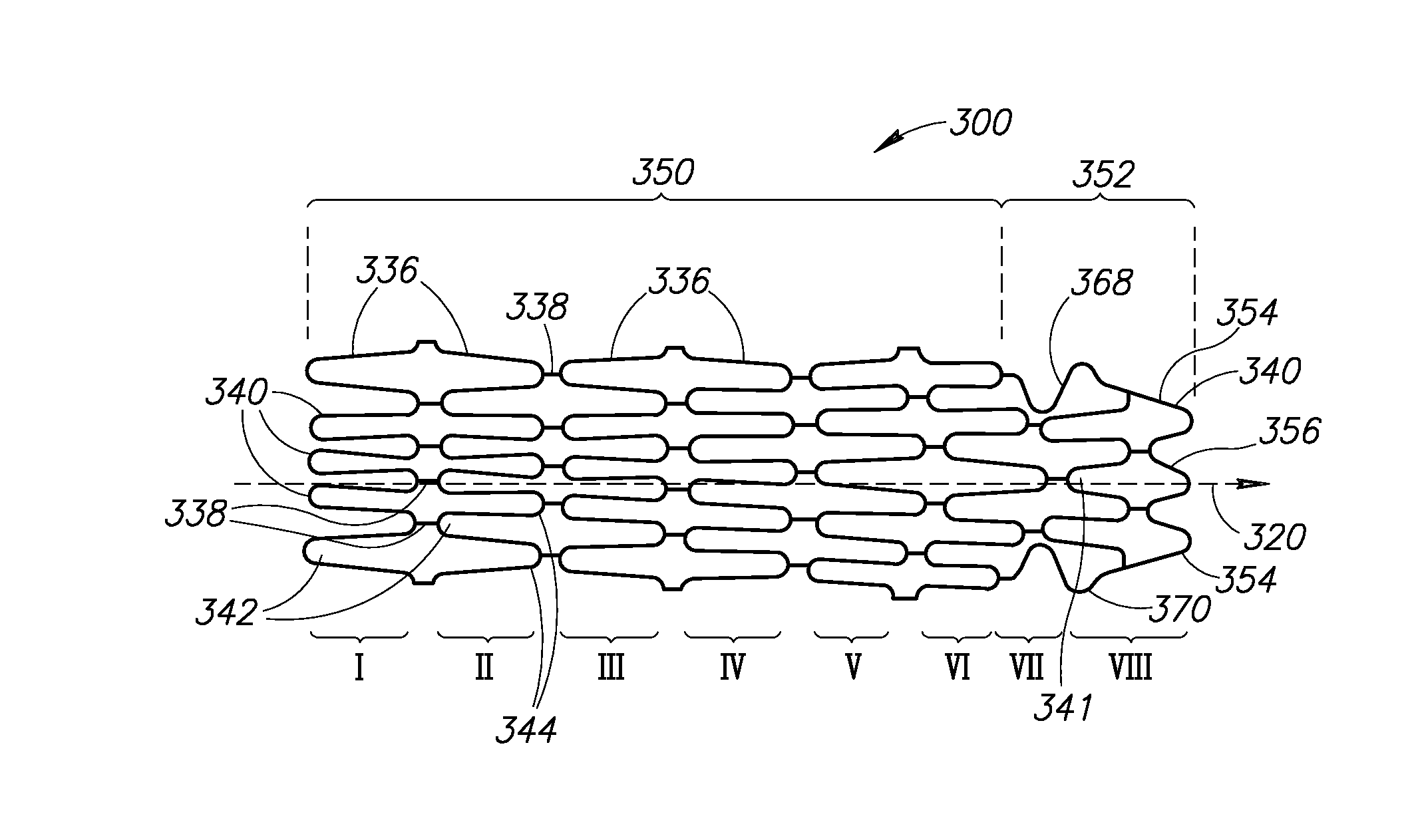
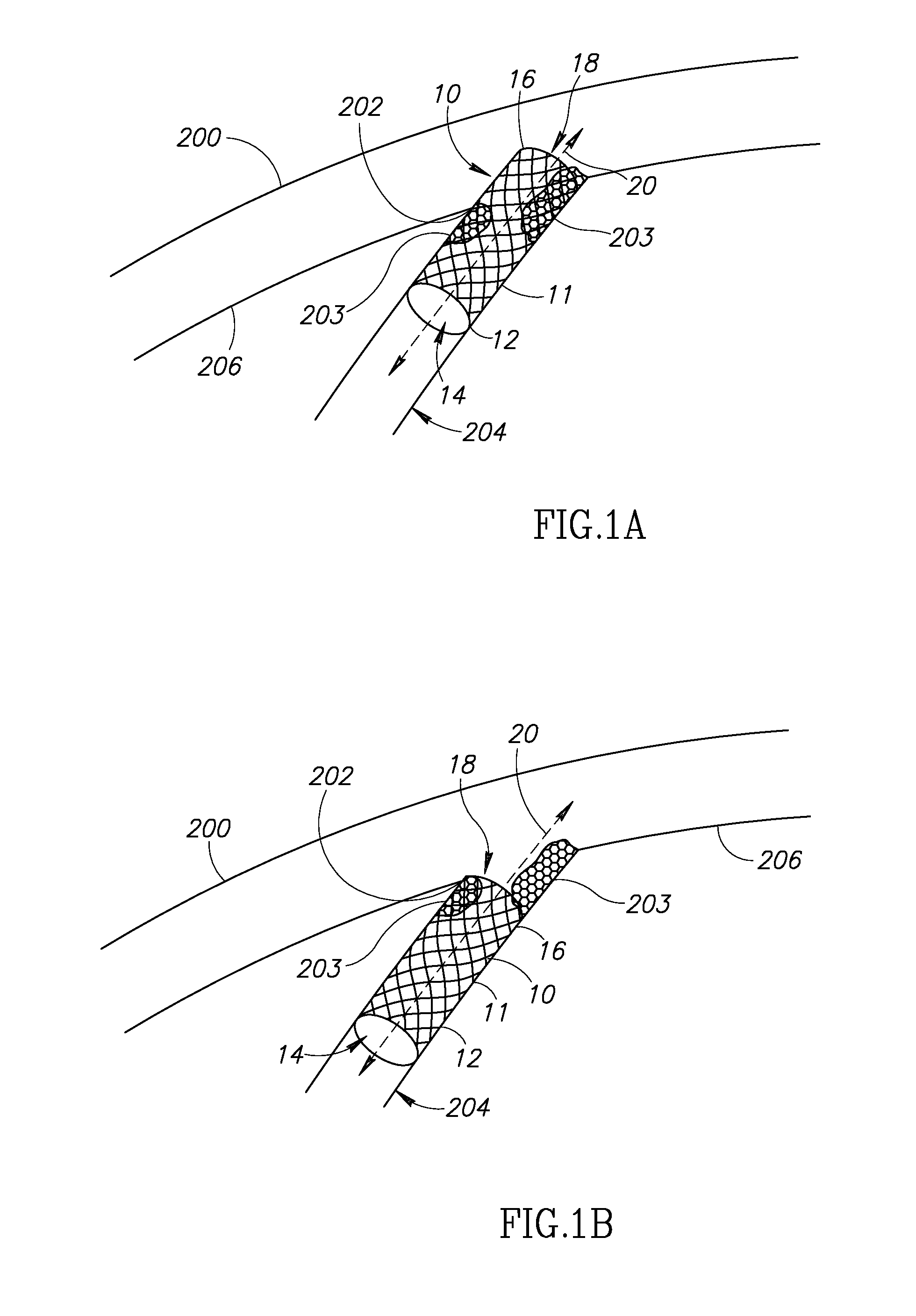
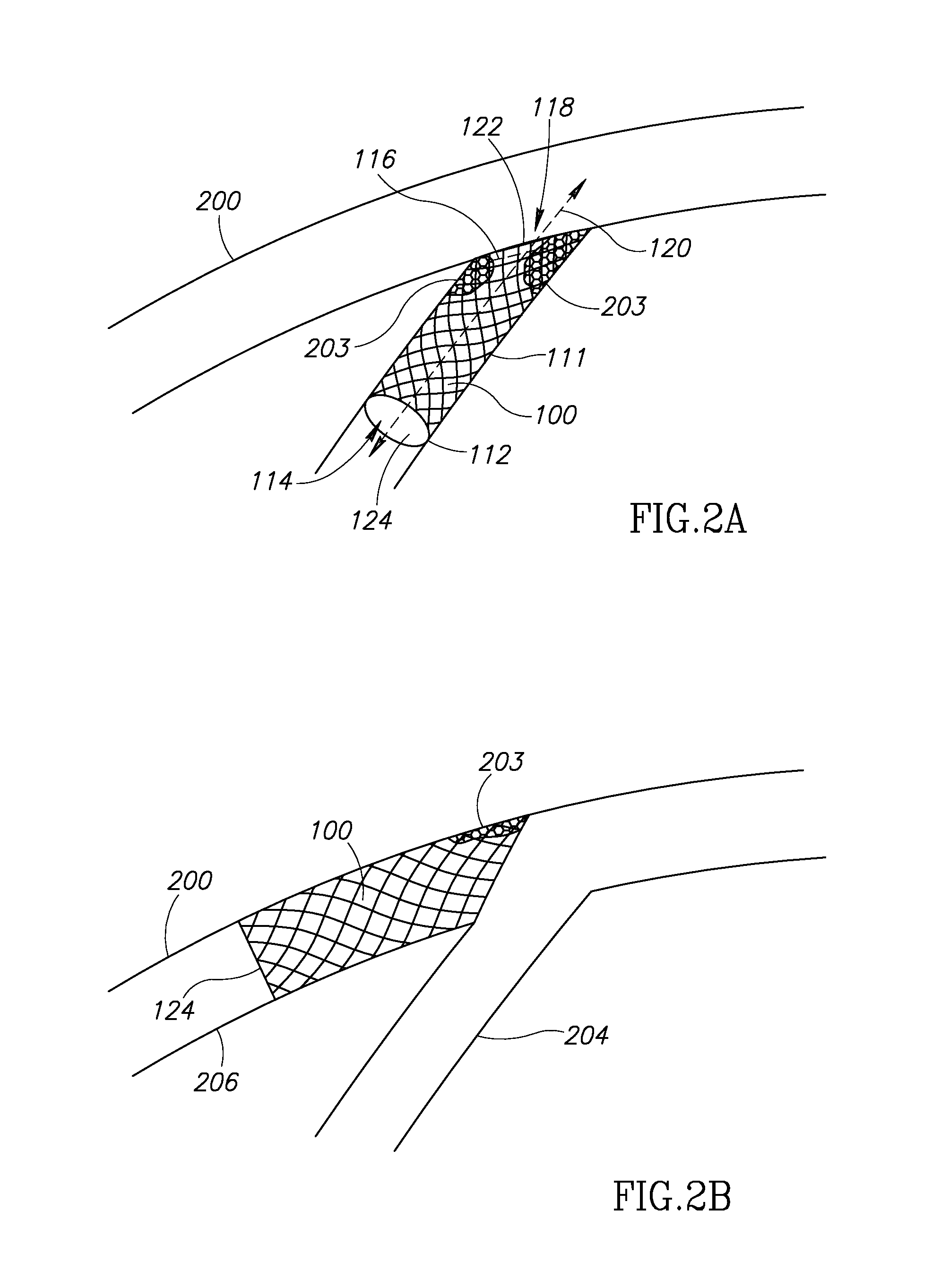
[0033]The present invention relates to a stent which has at least one oblique end in its expanded state. Further advantages of the design of the catheter of the present invention will be described herein below.

[0034]Before explaining at least one embodiment of the invention in detail, it is to be understood that the invention is not limited in its application to the details of construction and the arrangement of the components set forth in the following description or illustrated in the drawings. The invention is capable of o...


PUM


Abstract

A stent having a main body with a proximal end and a distal end section having proximal and distal openings used for treatment of lesions in blood vessels and hollow organs, particularly at the ostium of side branches. The stent adapts to the anatomical configuration of a vessel branch by having at least one oblique end section in at least its expanded state. Truncated versions of the oblique end section are described as well.

Description

FIELD OF THE INVENTION[0001]The present invention is directed to a stent used to treat a bifurcation. More specifically, the present invention is directed to an oblique stent wherein in an expanded state, at least one end of the stent is at an angle to a plane which is perpendicular to a longitudinal axis of the stent.BACKGROUND OF THE INVENTION[0002]Stents are prostheses which may be made out of metal and may be either balloon expandable or self expandable, or which may be made out of a polymer. Stents are used for scaffolding or dilatation of diseased segments in hollow organs, particularly in blood vessels, which may be applied by use of catheter techniques, as used in heart catheterization and angioplasty procedures. Stents are made of wire-like materials or cut from tubes by laser cutting techniques or other techniques such as etching. The wire-like mesh forming the tubular wall of the stents includes struts (stent material) and gaps between the struts (no material). The struts...

Claims


Application Information

Patent Timeline
Patent Type & Authority Applications(United States)
IPC IPC(8): A61F2/82
CPCA61F2/82A61F2/915A61F2002/821A61F2002/91558A61F2230/0008A61F2250/0026
Inventor ISCHINGER, THOMASSOLAR, RONALD JAYLIEBER, GLEN
Owner CURAVAS GMBH
Why Eureka
Try Eureka