Numerical Method to determine a system anomaly using as an example: A Gas Kick detection system.

Inactive Publication Date: 2014-09-18
BOLLINGHAM LEONARD ALAN
6 Cites 0 Cited by

AI-Extracted Technical Summary

Problems solved by technology

Tested against actual blowouts and controlled lab experiments this simulator proved incredibly accurate, but nothing to solve this detection problem.
The problem was to devise a method to detect the gas kick, and stop it in the...

Benefits of technology

[0016]This system is much simpler as one single pulse is created each interval of a second or two. There isn't any binary concerns by the sending unit, so the cost of the sending unit is greatly reduced. It works in stationary directional drilling, and al...

Abstract

This numerical method creates a mesh of tracers or indicators within a simulator which help determine what various anomalies may look like in real time applications. In this situation, determining gas kicks while drilling for oil and preventing blowouts: This application will provide more stable dependable message passing, reservoir data from the kick, production facility design criteria, and of course better prevent disasters.

Application Domain

ConstructionsVolume/mass flow measurement +4

Technology Topic

Message passingPetroleum +2

Image

  • Numerical Method to determine a system anomaly using as an example:  A Gas Kick detection system.
  • Numerical Method to determine a system anomaly using as an example:  A Gas Kick detection system.
  • Numerical Method to determine a system anomaly using as an example:  A Gas Kick detection system.

Examples

  • Experimental program(1)

Example

IDENTIFICATION OF PARTS/COMPONENTS OF INVENTION
[0020] 10 Control unit in idle state (FIG. 1) [0021] 20 Sending Unit [0022] 30 Signals in normal intervals (FIG. 1) [0023] 40 Signals before gas kick are compressed (FIG. 20) [0024] 50 Signals after gas kick are separated farther apart (FIG. 2) [0025] 70 Control unit in alert state (FIG. 2) [0026] 80 BOP normal state, open (FIG. 1) [0027] 90 BOP kick state, closed (FIG. 2) [0028] 100 Mud Tank [0029] 200 Well at the surface [0030] 300 Well at the drilled depth [0031] 400 High Pressure Gas Zone
DETAILED DESCRIPTION AND BEST IMPLEMENTATION
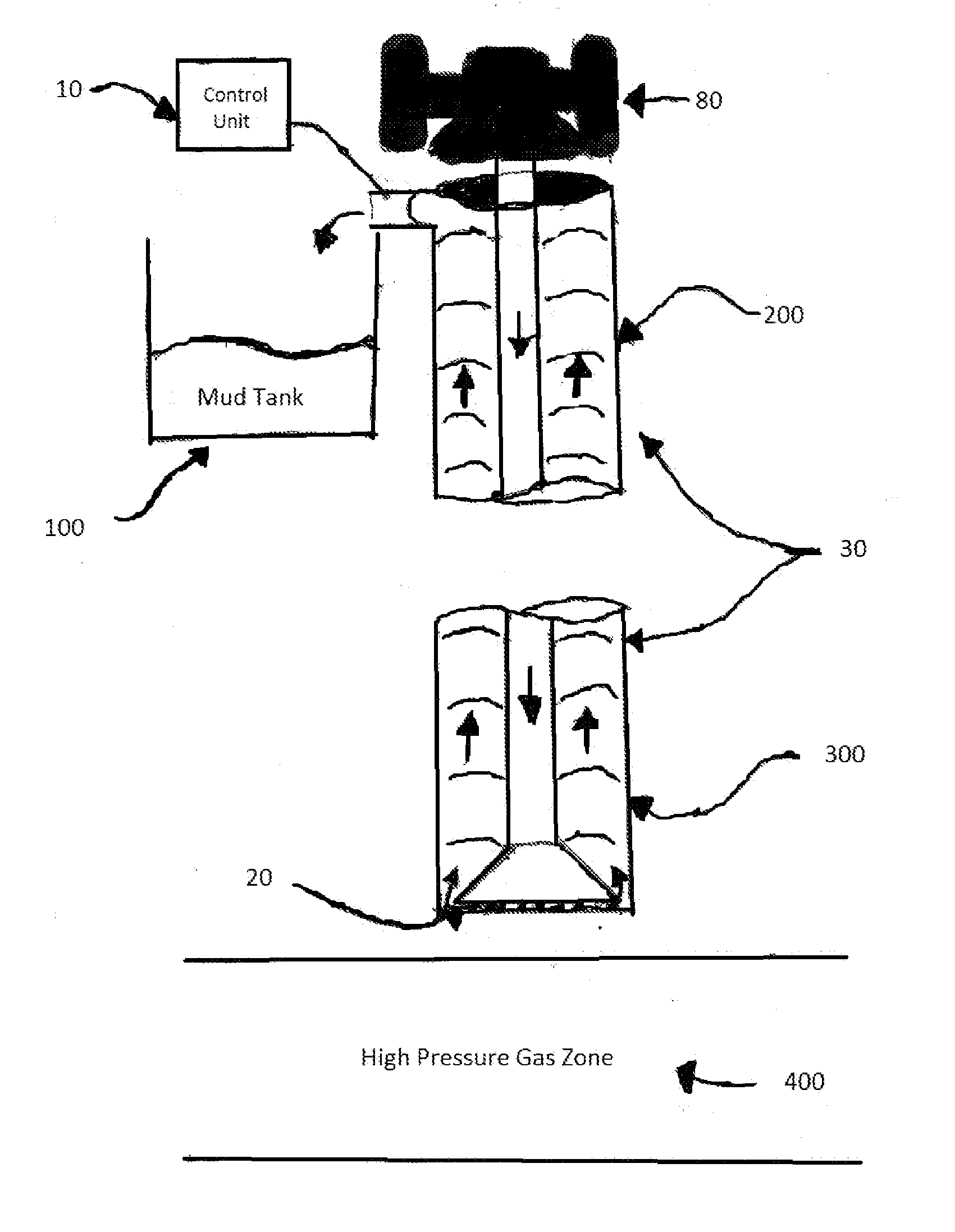
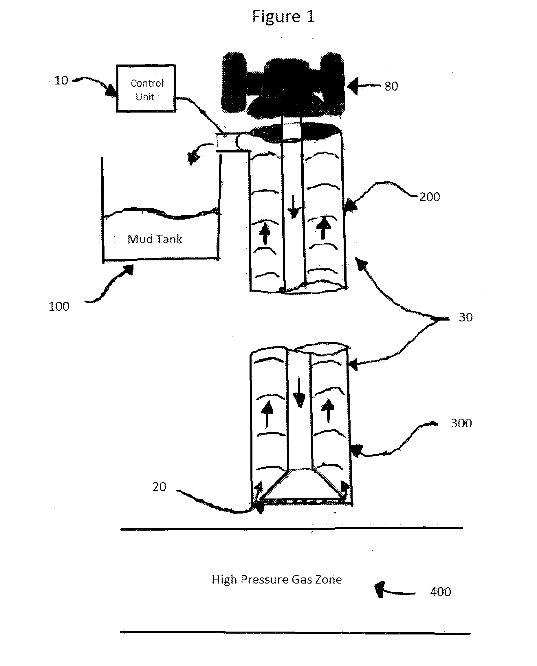
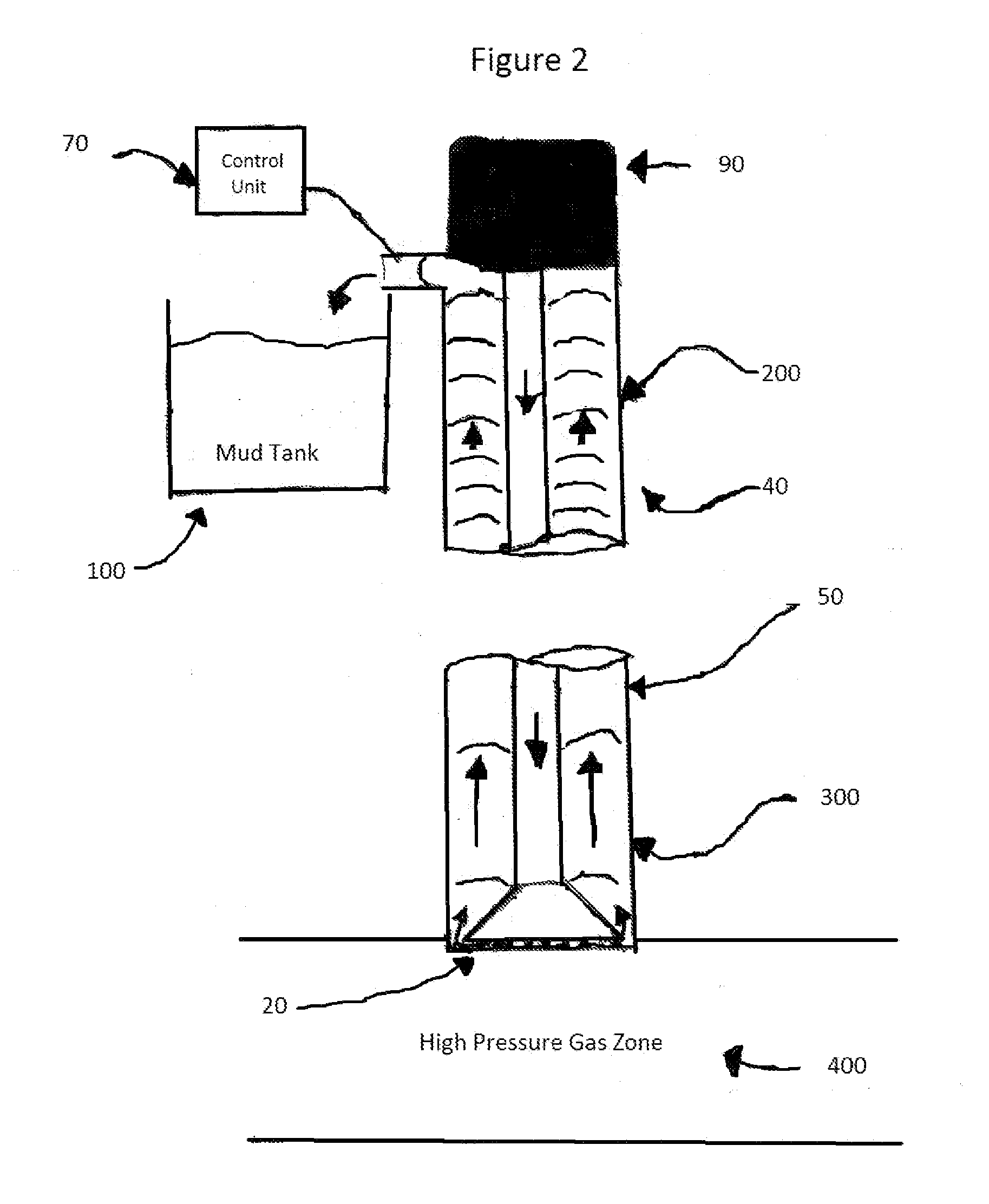
[0032]The “Bollingham Technique” is used in this Blow Out detection system by placing sending unit on the collar or as part of the drillbit (20). A receiving unit is placed at the surface (10). The system begins normal operation with an open BOP (80). The sending unit acts as a notification of a gas kick (70) as the column is full of even spaced messages which get compressed due to the increase in the speed of the mud flow. The control unit is also simulating the progress of the gas kick given the information gathered. This allows for time to close the preventer: The BOP is closed in plenty of time to stop a disaster (90). In fact, the sooner the better as heavier mud can be circulated into the well to offset the kick pressure. This method can work minutes faster than any other system.
[0033]The sending and receiving technology were first used in the 70s for directional drilling. To design a system to detect gas kicks using the “Bollingham Technique” is new as is the special sending unit (20), and the logic unit is new (10, 70). Making use of a stable constant pulse messaging technology to detect a Doppler like affects or a compression of the interval between received messages which can only be caused by extreme pressure of gas and oil entering the annulus from a newly discovered producing zone/reservoir. The gas kick causes extra volume to enter the well, and this cause an acceleration of the mud column out of the borehole. This acceleration causes a reduction in the interval of the messages at the top of the well detected by the receiver. This information can be used to quickly stop drilling to minimize the amount of gas that enters which is critical. Drilling can possibly stop in just seconds. With the simulation and such exact measurement of where the top of the gas kick is located, the reservoir information given during the blowout can indicate all sorts of great things about the reservoir. Pressure, permeability, etc all can be closely estimated from the message passing information that is recorded. Current art cannot tell where the top of the gas kick is, and this causes the BOP to be closed in cases where circulating heavier mud can alleviate the problem. A controllable choke can be used, with the safe time necessary to close the BOP always allowed before the gas kick reaches the surface.
[0034]Shallow blowouts are the most dangerous as there is virtually no time from the kick to the blow out. The simulator can use drill depth to determine the safe depth at which a gas kick can be detected and the BOP can be closed without issues. This is a very simple and effective system.
[0035]A detection system has been simulated that is placed on the drill string up a sufficient distance from the sending unit. This completes a real GasKick/BlowOut detection system built according to the “Bollingham Technique”, which involves a proprietary sending unit at the drill bit, a receiving/logic unit at the surface which displays gas kick activity in the annulus, and can alert the crew to close the BOP. The receiving unit detects changes in the patterns of the information received due to extra velocity in the annulus which causes Doppler or Doppler-like affects in the annular mud which indicates a gas kick has entered the annulus. Different types of pulses are used so that one type may work better than the others but at least the kick will be discovered as quickly as possible. Several types of messages, sounds, pulses, and configurations can be used to find the quickest way to detect that a gas kick has entered the annular drill space. A sending unit that can transmit fluid pulses, sound, or combinations of signals in any format or interval. A receiving/control unit that can interpret mud speed, signal speed and intervals, and make logical decisions to alert the crew or just monitor. This type of system can be added to any simulation in any study which deals with detection of some known type of motion or anomaly which can be simulated. A speaker system can be playing the signal received, and everyone on the drilling floor can hear the ever increasing pace of the signal as the gas kick races to the surface. The progress of the kick can be simulated from this signal information and other known factors of the drilling progress and systems. The progress can also alert the crew to prepare for trouble, watch the mud tank for greater than normal gains which is a great indicator of extras in the annular space.
[0036]In FIG. 1 the “Bollingham Technique” is in the start or normal mode where drilling is normal the signals are evenly spaced, and the mud is flowing at a constant rate (30). In FIG. 2 the “Bollingham Technique” is in the alert mode where a high pressure zone is drilled into, the signals in the annular space start being compressed (40), and the signals sent after the kick enters the well are stretched out more and more as the mud and gas start to move very fast (50).
[0037]There can be many scenarios of message design, as many were tried by adding sound waves and fluid pulse riders to the drilling mud as it left the drill bit. These were tracked to show patterns under all sorts of conditions and proved to be very indicative of trouble. The “Bollingham Technique” involves any type of signal/reception. What is important is detecting the dangerous new presence as quickly as possible and safely handling the problem.
[0038]One simulation shows the one second time slices to be 1 foot long under normal conditions of a constant drilling mud flow and no extra oil or gas coming into the borehole. At 30 seconds after the gas kick has started the 1 second time slices are over 2 feet long. Time intervals at the surface are now 0.95 seconds. If the message passing can be trusted then 0.05 seconds difference is worth taking the chance of stopping drilling to check for a gas kick. At 100 seconds after the gas kick has begun the 1 second time slices are over 10 feet in length. The density of the mud is dropping and the gas is expanding while more oil and gas are blasting into the borehole annular space. All of this information tells exactly what the reservoir is capable of producing. The top of the gas kick is racing toward the surface, and the surface time slices are about 0.90 seconds. Drilling has hopefully been stopped.
[0039]The current art still would have no clue anything is going on. Only the level of gas or noise at the drillbit is detected, and hopefully the message is not lost or damaged in transition. The current art trusts that the message will outpace the gas kick. There is no way to know where the gas kick has reached in the borehole. There is no collection of production information from the reservoir during the gas kick. Still this is the best the industry has in an incredibly difficult system of problems.
[0040]At this time the BOP should be closing or closed and precautions to circulate and handle the kick should be taken. Alarms can be going off, and all hands are working to control this horrific emergency before it gets out of control. If not, at 200 seconds the 1 second intervals at the drill bit are over 25 ft long. There is no detection of gas or oil, but just a decrease in the interval times of the mud pulses at the surface. The BOP is closed without question, and the disaster is prevented.
[0041]I do not have actual BOP details to simulate how it looks but this is something I hope to add in the future as detailed limitations and operating specifics can be added to the simulation which is monitoring and helping to control these disasters in real time. Understand that my simulation has no controls it just shows with no detection how fast the blowouts occur. When the gas and oil come out the well the fluid is moving at over 100 mph. Sand hits any metal and a spark occurs. Total disaster ensues. I know we can stop these with this numerical method simulation driven real time system and known/proven industry hardware. Companies, lives, nature, property, and the reservoir are damaged or lost.
[0042]When 6′ of oil and gas enter the borehole in one second at the bottom, SIX one second intervals pass through the detection point at the top. Instead of 1 second intervals they are ⅙th of a second intervals. It isn't exact because oil mud compresses somewhat. However, it is enough to know there is a problem. So the instant it happens, the expected signal at the top is indicating successfully. Safety and other concerns can be started as the minimum time required to close the BOP can be assured. This floored me as the investigator, I have tried so many things over the years. This is phenomenal! Thank you sincerely.

PUM

no PUM

Description & Claims & Application Information

We can also present the details of the Description, Claims and Application information to help users get a comprehensive understanding of the technical details of the patent, such as background art, summary of invention, brief description of drawings, description of embodiments, and other original content. On the other hand, users can also determine the specific scope of protection of the technology through the list of claims; as well as understand the changes in the life cycle of the technology with the presentation of the patent timeline. Login to view more.

Similar technology patents

Algorithm for quantitative standing balance assessment

InactiveUS20120253233A1cost reduction
Owner:CARE INNOVATIONS LLC

Battery assembly

ActiveUS20110104532A1low mass designcost reduction
Owner:ENERDEL

Method and apparatus for creating optical images

ActiveUS20080130309A1reduced electrical requirementcost reduction
Owner:DRAGONFISH TECH

Classification and recommendation of technical efficacy words

  • cost reduction

Gas-phase chemical reactor and method of using same

ActiveUS20190376180A1less wastefulcost reduction
Owner:ASM IP HLDG BV

Drilling system and method

InactiveUS20020112888A1cost reductioneliminate time
Owner:IMPACT ENG SOLUTIONS +2

System and method for remote asynchronous data replication

ActiveUS20090030986A1cost reductionwithout increase bandwidth requirement
Owner:EMC IP HLDG CO LLC
Why Eureka
Try Eureka