Shift-by-wire actuation of a transmission park brake

Active Publication Date: 2014-09-25
FORD GLOBAL TECH LLC
View PDF2 Cites 8 Cited by
  • Summary
  • Abstract
  • Description
  • Claims
  • Application Information

AI Technical Summary

Benefits of technology

The patent describes a transmission park-brake system that includes multiple pressure sources and a servo valve to engage or disengage the park-brake using different sources. The system prevents loss of park-engagement due to a single point failure and has a decoupling feature that allows for park-engagement even if there is a failure in the solenoid. The technical effects of this system include improved safety and reliability of the transmission.

Problems solved by technology

The system does not permit loss of park-engagement due to a single point failure.

Method used


Image

  • Shift-by-wire actuation of a transmission park brake
  • Shift-by-wire actuation of a transmission park brake

Examples


Embodiment Construction

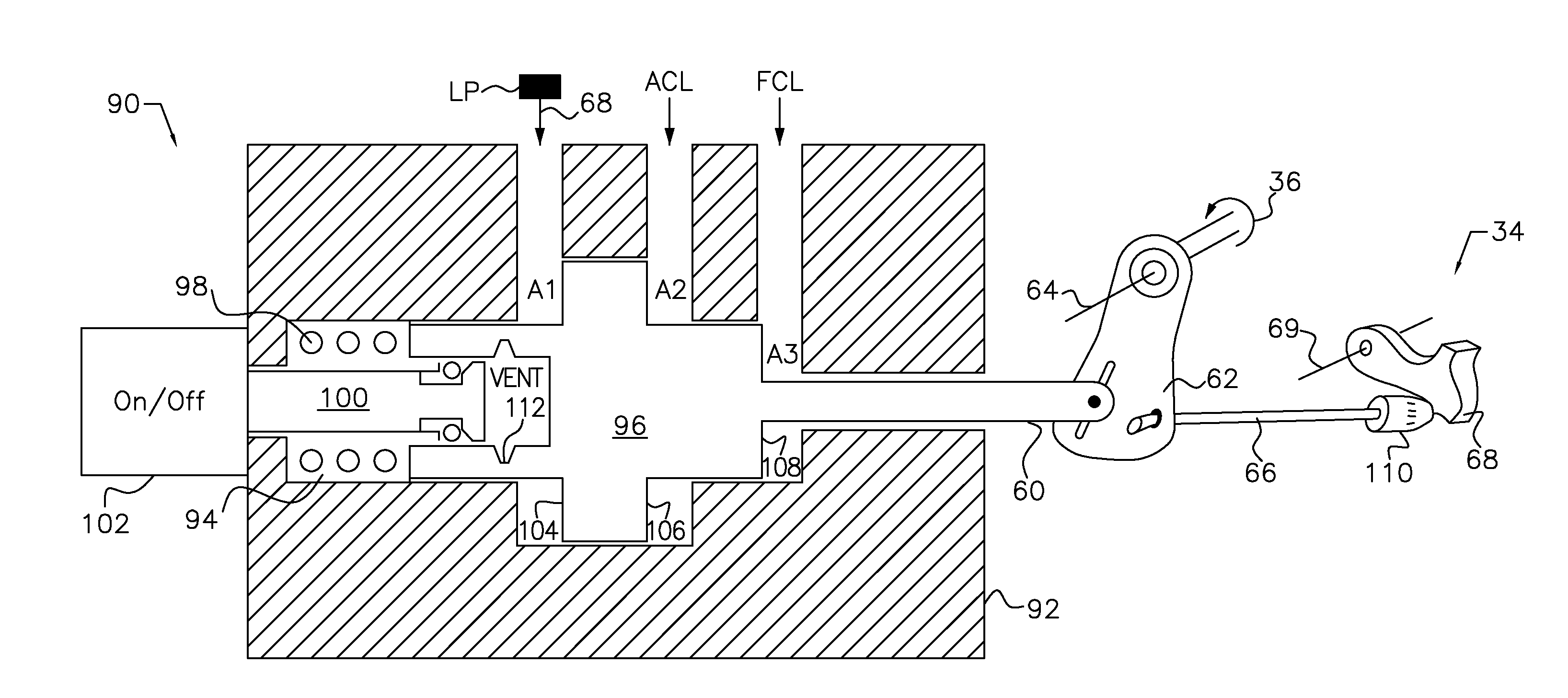
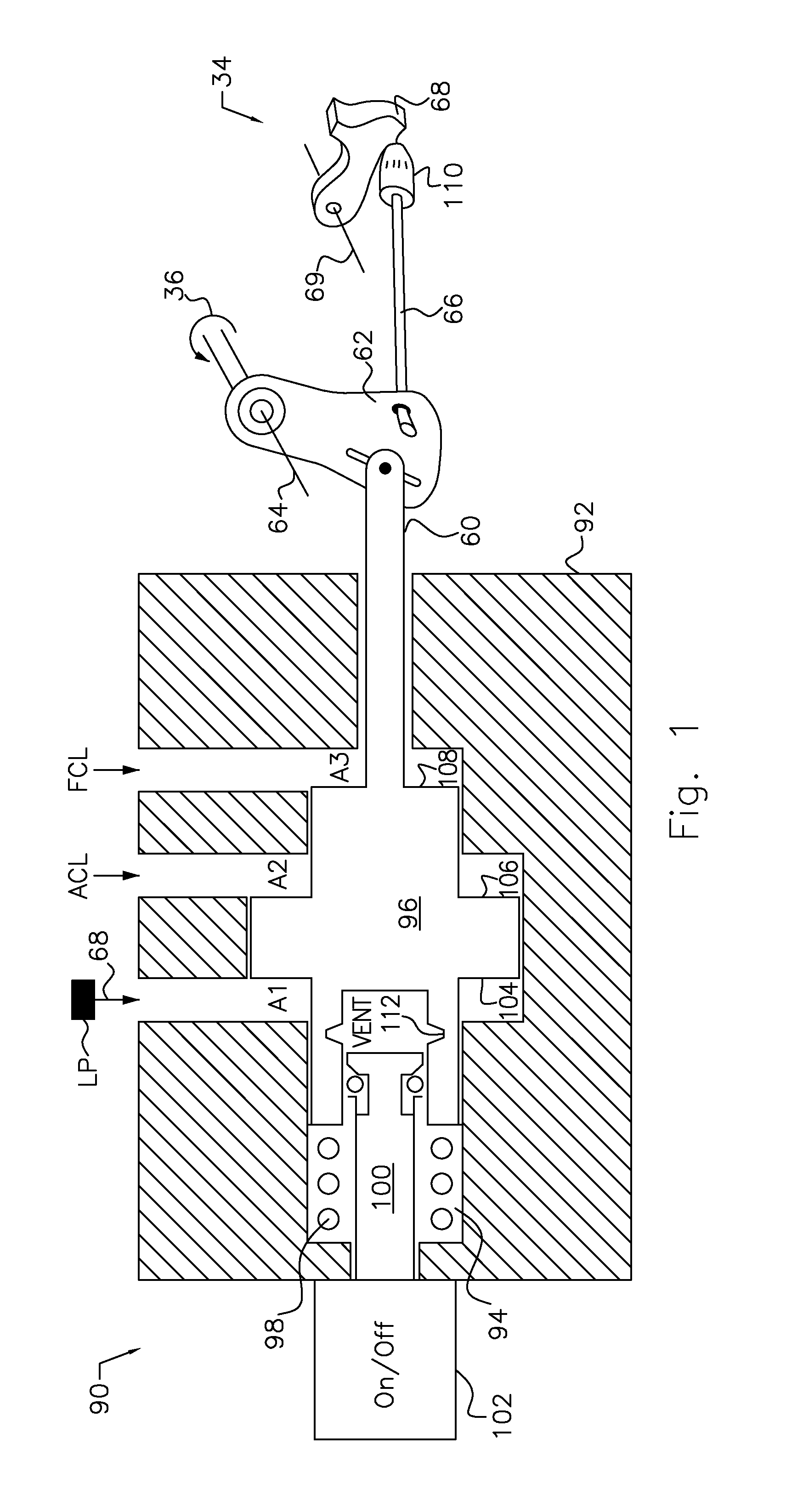
[0012]FIG. 1 is a schematic diagram of a park servo valve 90. Valve 90 includes a body 92 formed with a cylinder 94 containing a valve spool 96, helically coiled compression spring 98 and the actuator 100 of an on / off, electro-mechanical latch solenoid 102. Spool 96 is formed with a first surface 104 having an area A1, a second surface 106 having an area A2, and a third surface 108 having an area A3. Spool 96 is connected by a rod 60, which is secured to crank arm 62. A park rod 66 is connected to crank arm 62 and to the bullet 110, which contacts pawl 68, which pivots about axis 69 into and out of engagement with a park gear, which is secured to the driven output of a vehicle transmission or is driveably connected to the vehicle wheels.

[0013]Crank arm 62 pivots about axis 64. A torsional spring 34 applies torque to the crank arm 62.

[0014]The actuator 100 of solenoid 102 is releaseably latched to spool 96 at a detent recess 112 and can be delatched when the solenoid is activated to ...


PUM


Abstract

A transmission park-brake system includes a transmission park brake, a solenoid, first, second and third pressure sources, and a servo valve for disengaging the park-brake using the first and second pressure sources, holding the park-brake disengaged using a force produced by the solenoid and one of the first and second pressure sources, and engaging the park-brake using the third pressure source.

Description

BACKGROUND OF THE INVENTION[0001]1. Field of the Invention[0002]This invention relates generally to an apparatus for engaging and disengaging a transmission park brake through hydraulic and electrical actuation rather than by mechanical actuation by the vehicle operator.[0003]2. Description of the Prior Art[0004]In an automatic transmission that employs a shift-by-wire (SBW) control Park, Reverse, Neutral and Drive ranges of the transmission are engaged and disengaged under electrical control. SWB systems have begun to replace the conventional shifter cable, which is used in automatic transmissions to control the park pawl and a hydraulic manual valve that feeds pressure to clutches that distinguishes the Neutral range from the Reverse and Drive ranges.[0005]SBW systems generally are of two types: (i) electromechanical having redundant hardware and supplemental power, and (ii) electro-hydraulic having a redundant electro-mechanical path. Electro-hydraulic SBW systems allow for reduc...

Claims


Application Information

Patent Timeline
IPC IPC(8): B60T11/10
CPCB60T11/10F16H63/38F16H63/483B60T1/005B60T1/062F16D63/006F16D2121/04F16D2121/20F16D2125/66
Inventor KINCH, DEREKFRAIT, STEVEN A.
Owner FORD GLOBAL TECH LLC
Why Eureka
Try Eureka